What is the I2C LCD Adapter Module ? Interfacing with Arduino ?
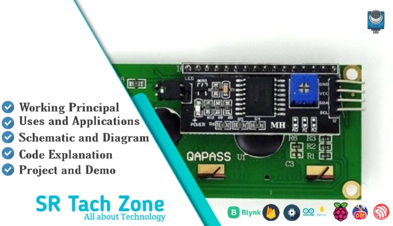
Welcome to the community! It’s always exciting to meet another tech enthusiast. This space is built by creators, for creators. Today, we’re diving into the I2C LCD Adapter Module. It’s a tiny board that turns a regular 16×2 or 20×4 LCD into something much easier to use with your microcontroller. No more wasting pins—just four wires and you’re good to go. Let’s break down how it works and how you can add a display to your projects without the usual headache.
What is I2C LCD Adapter Module?
The I2C LCD Adapter Module (often called an I2C backpack) is a small expansion board that connects to the 16-pin header of a standard character LCD (like 16×2 or 20×4). Consequently, it reduces the number of connections from up to 16 pins down to just 4 using the I2C protocol. This module uses the PCF8574 or PCF8574A I2C port expander chip. Therefore, it lets you control the LCD with only SDA and SCL lines, plus power. Additionally, it includes a contrast potentiometer, backlight jumper, and address selection jumpers for connecting multiple displays.
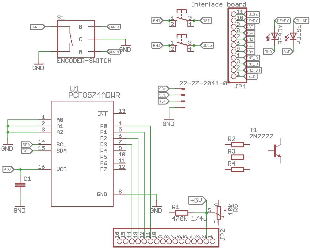
Working Principles of I2C LCD Adapter Module?
I2C Port Expansion: First, the PCF8574 chip provides 8 I/O pins that can be controlled over I2C. As a result, these pins handle the LCD’s data (4-bit mode), RS, Enable, and backlight signals.
4-Bit Communication: Moreover, the adapter operates the LCD in 4-bit mode, sending data in two nibbles. Consequently, only 4 data lines (D4-D7) are needed instead of 8.
Backlight and Contrast Control: In addition, the module routes the backlight through a transistor (controlled via I2C) and includes a potentiometer for manual contrast adjustment.
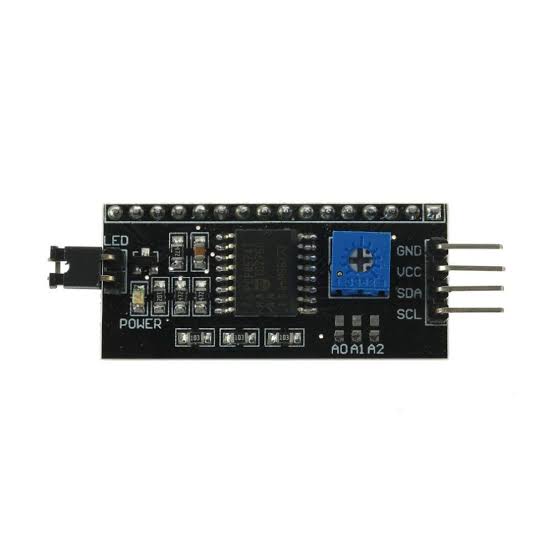
Hardware Overview of I2C LCD Adapter Module?
The module is a small PCB that solders or plugs onto the back of a standard HD44780-compatible LCD. It features the PCF8574 chip, a potentiometer, jumpers, and a 4-pin header.
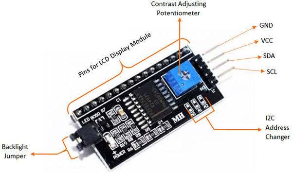
Most boards have address jumpers (A0-A2) to set the I2C address (default 0x27 or 0x3F). As a result, you can connect up to 8 displays on the same bus.
Supporting Circuitry: Additionally, it includes pull-up resistors for I2C lines and a backlight control circuit. Consequently, the whole setup remains simple and reliable.
Technical Specifications of I2C LCD Adapter Module?
- Function: I2C interface for HD44780 character LCDs.
- Chip: PCF8574 or PCF8574A I2C expander.
- I2C Address: 0x20–0x27 (default 0x27) or 0x38–0x3F (configurable via jumpers).
- Operating Voltage: 5V (some support 3.3V).
- LCD Mode: 4-bit parallel.
- Backlight Control: On/Off via I2C.
- Contrast Adjustment: Onboard potentiometer.
- Pinout: VCC, GND, SDA, SCL.
I2C LCD Adapter Module Pinout?
- VCC: Power supply (5V)
- GND: Ground
- SDA: I2C data line (A4 on Uno)
- SCL: I2C clock line (A5 on Uno)
Using I2C LCD Adapter Module with Arduino
In this part, we will learn how you can use the I2C LCD Adapter with a 16×2 LCD and Arduino Uno, Nano, or Mega to display text in just a few minutes – even if you’re a beginner.
What You Need:
- Any Arduino board (Uno recommended)
- 16×2 or 20×4 LCD with I2C adapter soldered
- Jumper wires
Wiring Diagram:
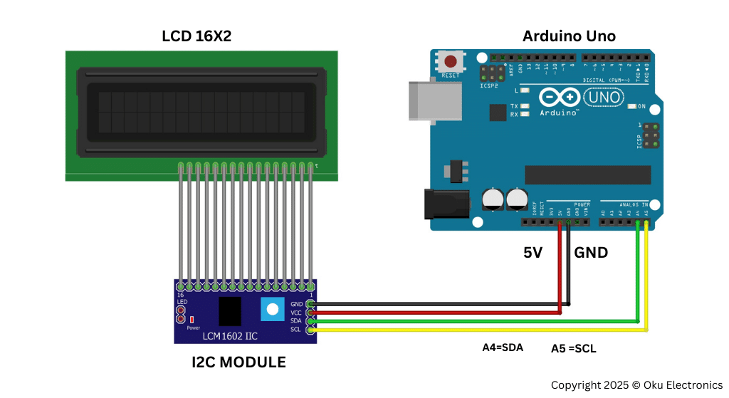
Basic Connections to Arduino:
- VCC: Connect to 5V on Arduino
- GND: Connect to Arduino GND
- SDA: Connect to A4 (Uno) or SDA pin
- SCL: Connect to A5 (Uno) or SCL pin
Code:
Install “LiquidCrystal_I2C” library by Frank de Brabander via Arduino IDE Library Manager before uploading. Here’s a tested simple code – just copy-paste into your Arduino IDE (change address if needed).
#include <Wire.h>
#include <LiquidCrystal_I2C.h>

// Set the LCD address (common: 0x27 or 0x3F)
LiquidCrystal_I2C lcd(0x27, 16, 2);  // 16 columns, 2 rows

void setup() {
  lcd.init();
  lcd.backlight();

  lcd.setCursor(0, 0);
  lcd.print("Hello, World!");
}

void loop() {
  // Add scrolling or dynamic text here if needed
}
Credit: This example uses the popular LiquidCrystal_I2C library by Frank de Brabander.
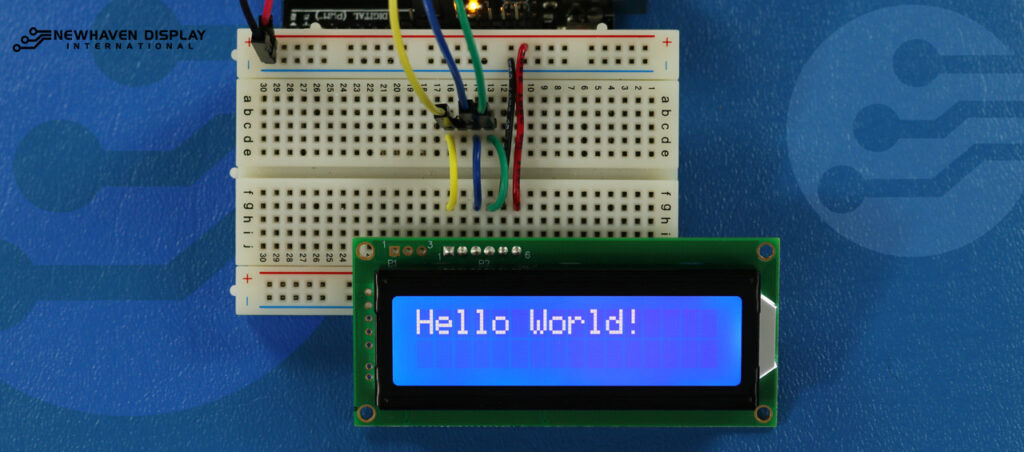
After uploading, adjust the contrast potentiometer if text is faint. You should see “Hello, World!” on the first line!
Wrapping up
That’s a wrap on today’s guide! I hope this walkthrough made it easier to understand how this component fits into your next big idea. Technology is all about experimenting and learning as you go. If something didn’t click, or if you’re hitting a wall with your wiring or code, don’t sweat it! Just drop a comment below. I’m always here to help you troubleshoot and get your project back on track.