Welcome to our repository of Arduino is a micro controller. The Arduino is a micro controller board that you can program to read information from the world around you and to send commands to the outside world (inputs and outputs). The Arduino is a great tool to start into electronics and programming and it is used worldwide by makers, students and even engineers. Arduino is an open-source electronics platform based on easy-to-use hardware and software. Arduino boards are able to read inputs – light on a sensor, a finger on a button, or a Twitter message – and turn it into an output – activating a motor, turning on an LED, publishing something online.
Get started with Arduino, we have free Arduino Tutorials and Project ideas. Using the next quick links, you’ll find all our Arduino Guides with easy to follow step-by-step instructions, circuit schematics, source code, images and videos.
Introduction with Ardunino
Arduino is an open-source platform used for building electronics projects. Arduino consists of both a physical programmable circuit board (often referred to as a microcontroller) and a piece of software, or IDE (Integrated Development Environment) that runs on your computer, used to write and upload computer code to the physical board. The Arduino IDE uses a simplified version of C++, making it easier to learn to program.
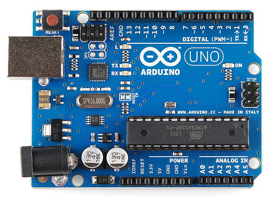
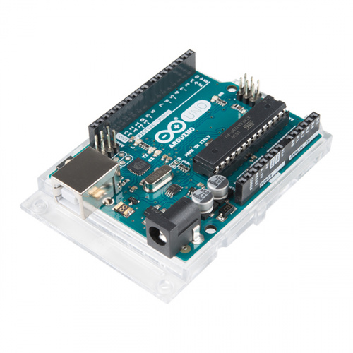
The Uno is one of the more popular boards in the Arduino family and a great choice for beginners. We’ll talk about what’s on it and what it can do later in the tutorial.
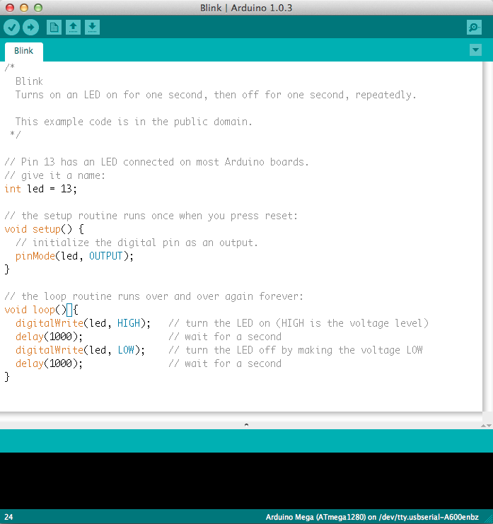
This is a screenshot of the Arduino IDE.
Believe it or not, those 10 lines of code are all you need to blink the on-board LED on your Arduino. The code might not make perfect sense right now, but, after reading this tutorial and the many more Arduino tutorials waiting for you on our site, we’ll get you up to speed in no time!
Suggested Reading
Arduino is a great tool for people of all skill levels. However, you will have a much better time learning along side your Arduino if you understand some Sensors, Modules, Display that can be use with Arduino. We recommend that you have at least a decent understanding of these concepts before you dive in to the wonderful world of Arduino.
What Does it Do?
The Arduino hardware and software was designed for artists, designers, hobbyists, hackers, newbies, and anyone interested in creating interactive objects or environments. Arduino can interact with buttons, LEDs, motors, speakers, GPS units, cameras, the internet, and even your smart-phone or your TV! This flexibility combined with the fact that the Arduino software is free, the hardware boards are pretty cheap, and both the software and hardware are easy to learn has led to a large community of users who have contributed code and released instructions for a huge variety of Arduino-based projects.
For everything from robots and a heating pad hand warming blanket to honest fortune-telling machines, and even a Dungeons and Dragons dice-throwing gauntlet, the Arduino can be used as the brains behind almost any electronics project.

And that’s really just the tip of the iceberg — if you’re curious about where to find more examples of Arduino projects in action
What’s on the board?
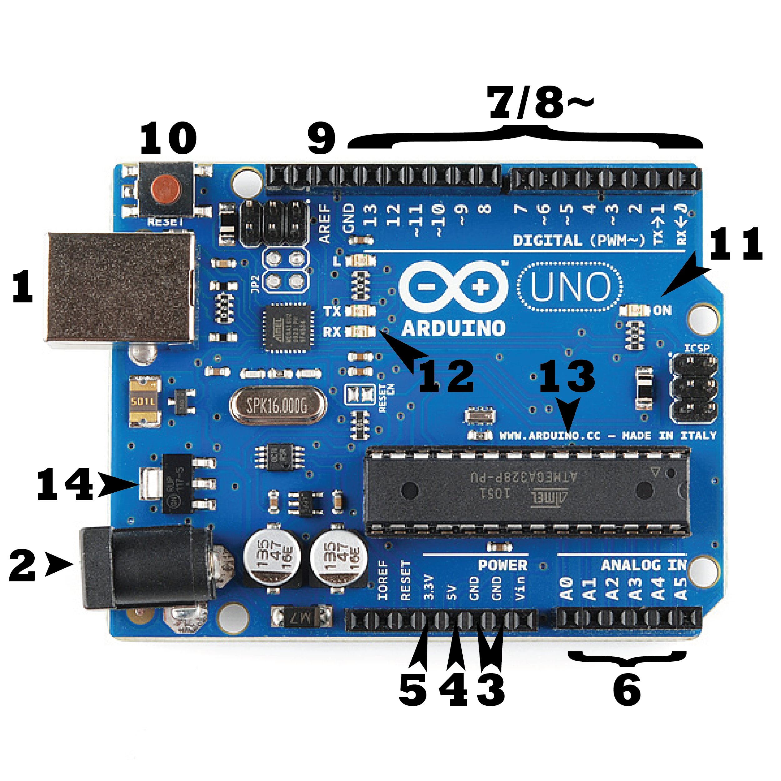
There are many varieties of Arduino boards that can be used for different purposes. Some boards look a bit different from the one below, but most Arduinos have the majority of these components in common:
Power (USB / Barrel Jack)
Every Arduino board needs a way to be connected to a power source. The Arduino UNO can be powered from a USB cable coming from your computer or a wall power supply that is terminated in a barrel jack. In the picture above the USB connection is labeled (1) and the barrel jack is labeled (2).
The USB connection is also how you will load code onto your Arduino board.
NOTE: Do NOT use a power supply greater than 20 Volts as you will overpower (and thereby destroy) your Arduino. The recommended voltage for most Arduino models is between 6 and 12 Volts.
Pins (5V, 3.3V, GND, Analog, Digital, PWM, AREF)
The pins on your Arduino are the places where you connect wires to construct a circuit (probably in conjuction with a breadboard and some wire. They usually have black plastic ‘headers’ that allow you to just plug a wire right into the board. The Arduino has several different kinds of pins, each of which is labeled on the board and used for different functions.
- GND (3): Short for ‘Ground’. There are several GND pins on the Arduino, any of which can be used to ground your circuit.
- 5V (4) & 3.3V (5): As you might guess, the 5V pin supplies 5 volts of power, and the 3.3V pin supplies 3.3 volts of power. Most of the simple components used with the Arduino run happily off of 5 or 3.3 volts.
- Analog (6): The area of pins under the ‘Analog In’ label (A0 through A5 on the UNO) are Analog In pins. These pins can read the signal from an analog sensor (like a temperature sensor) and convert it into a digital value that we can read.
- Digital (7): Across from the analog pins are the digital pins (0 through 13 on the UNO). These pins can be used for both digital input (like telling if a button is pushed) and digital output (like powering an LED).
- PWM (8): You may have noticed the tilde (~) next to some of the digital pins (3, 5, 6, 9, 10, and 11 on the UNO). These pins act as normal digital pins, but can also be used for something called Pulse-Width Modulation (PWM). These pins as being able to simulate analog output (like fading an LED in and out).
- AREF (9): Stands for Analog Reference. Most of the time you can leave this pin alone. It is sometimes used to set an external reference voltage (between 0 and 5 Volts) as the upper limit for the analog input pins.
Reset Button
Just like the original Nintendo, the Arduino has a reset button (10). Pushing it will temporarily connect the reset pin to ground and restart any code that is loaded on the Arduino. This can be very useful if your code doesn’t repeat, but you want to test it multiple times. Unlike the original Nintendo however, blowing on the Arduino doesn’t usually fix any problems.
Power LED Indicator
Just beneath and to the right of the word “UNO” on your circuit board, there’s a tiny LED next to the word ‘ON’ (11). This LED should light up whenever you plug your Arduino into a power source. If this light doesn’t turn on, there’s a good chance something is wrong. Time to re-check your circuit!
TX RX LEDs
TX is short for transmit, RX is short for receive. These markings appear quite a bit in electronics to indicate the pins responsible for serial communication. In our case, there are two places on the Arduino UNO where TX and RX appear — once by digital pins 0 and 1, and a second time next to the TX and RX indicator LEDs (12). These LEDs will give us some nice visual indications whenever our Arduino is receiving or transmitting data (like when we’re loading a new program onto the board).
Main IC
The black thing with all the metal legs is an IC, or Integrated Circuit (13). Think of it as the brains of our Arduino. The main IC on the Arduino is slightly different from board type to board type, but is usually from the ATmega line of IC’s from the ATMEL company. This can be important, as you may need to know the IC type (along with your board type) before loading up a new program from the Arduino software. This information can usually be found in writing on the top side of the IC. If you want to know more about the difference between various IC’s, reading the datasheets is often a good idea.
Voltage Regulator
The voltage regulator (14) is not actually something you can (or should) interact with on the Arduino. But it is potentially useful to know that it is there and what it’s for. The voltage regulator does exactly what it says — it controls the amount of voltage that is let into the Arduino board. Think of it as a kind of gatekeeper; it will turn away an extra voltage that might harm the circuit. Of course, it has its limits, so don’t hook up your Arduino to anything greater than 20 volts.
The Arduino Family
Arduino makes several different boards, each with different capabilities. In addition, part of being open source hardware means that others can modify and produce derivatives of Arduino boards that provide even more form factors and functionality. If you’re not sure which one is right for your project, here are a few options that are well-suited to someone new to the world of Arduino:
Arduino Uno (R3)
The Uno is a great choice for your first Arduino. It’s got everything you need to get started, and nothing you don’t. It has 14 digital input/output pins (of which 6 can be used as PWM outputs), 6 analog inputs, a USB connection, a power jack, a reset button and more. It contains everything needed to support the microcontroller; simply connect it to a computer with a USB cable or power it with a AC-to-DC adapter or battery to get started.
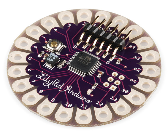
LilyPad Arduino
This is LilyPad Arduino main board! LilyPad is a wearable e-textile technology developed by Leah Buechley and cooperatively designed by Leah and SparkFun. Each LilyPad was creatively designed with large connecting pads and a flat back to allow them to be sewn into clothing with conductive thread. The LilyPad also has its own family of input, output, power, and sensor boards that are also built specifically for e-textiles. They’re even washable!
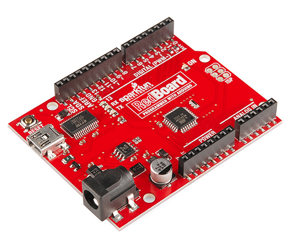
RedBoard
At SparkFun we use many Arduinos and we’re always looking for the simplest, most stable one. Each board is a bit different and no one board has everything we want — so we decided to make our own version that combines all our favorite features.
The RedBoard can be programmed over a USB Mini-B cable using the Arduino IDE. It’ll work on Windows 8 without having to change your security settings (we used signed drivers, unlike the UNO). It’s more stable due to the USB/FTDI chip we used, plus it’s completely flat on the back, making it easier to embed in your projects. Just plug in the board, select “Arduino UNO” from the board menu and you’re ready to upload code. You can power the RedBoard over USB or through the barrel jack. The on-board power regulator can handle anything from 7 to 15VDC.
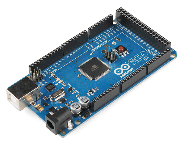
Arduino Mega (R3)
The Arduino Mega is like the UNO’s big brother. It has lots (54!) of digital input/output pins (14 can be used as PWM outputs), 16 analog inputs, a USB connection, a power jack, and a reset button. It contains everything needed to support the microcontroller; simply connect it to a computer with a USB cable or power it with a AC-to-DC adapter or battery to get started. The large number of pins make this board very handy for projects that require a bunch of digital inputs or outputs (like lots of LEDs or buttons).
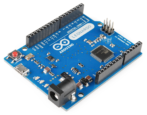
Arduino Leonardo
The Leonardo is Arduino’s first development board to use one microcontroller with built-in USB. This means that it can be cheaper and simpler. Also, because the board is handling USB directly, code libraries are available which allow the board to emulate a computer keyboard, mouse, and more!
The Extended Family
While your Arduino board sure is pretty, it can’t do a whole lot on its own — you’ve got to hook it up to something. There are lots of tutorials here on learn as well as the links back in the ‘What does it do’ section, but rarely do we talk about the general kinds of things you can easily hook into. In this section we’ll introduce basic sensors as well as Arduino shields, two of the most handy tools to use in bringing your projects to life.
Sensors
With some simple code, the Arduino can control and interact with a wide variety of sensors – things that can measure light, temperature, degree of flex, pressure, proximity, acceleration, carbon monoxide, radioactivity, humidity, barometric pressure, you name it, you can sense it!
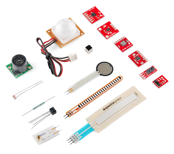
Just a few of the sensors that are easily compatible with Arduino
Shields
Additionally, there are these things called shields — basically they are pre-built circuit boards that fit on top of your Arduino and provide additional capabilities.
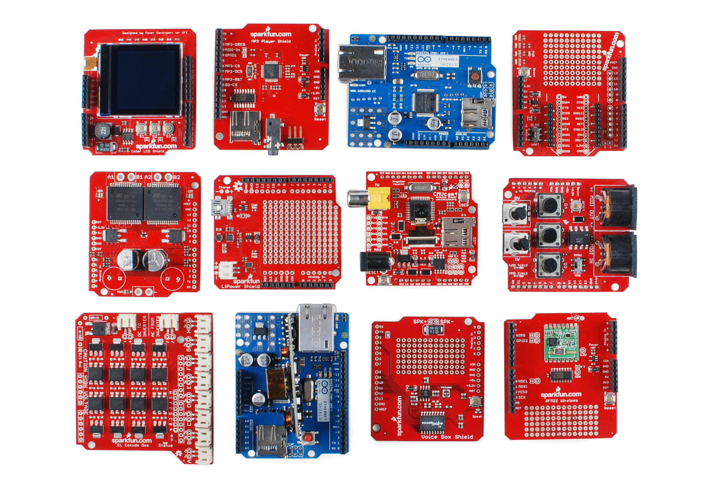
A partial selection of available shields to extend the power of your Arduino
Installing Arduino IDE
This tutorial will walk you through downloading, installing, and testing the Arduino software (also known as the Arduino IDE – short for Integrated Development Environment). Before you jump to the page for your operating system, make sure you’ve got all the right equipment.
Required Materials
To follow along with this tutorial, you will need the following materials. You may not need everything though depending on what you have. Add it to your cart, read through the guide, and adjust the cart as necessary.
- A computer (Windows, Mac, or Linux)
- An Arduino-compatible microcontroller (anything from this guide should work)
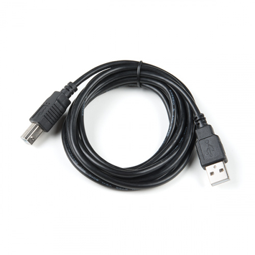
- A USB A-to-B cable, or another appropriate way to connect your Arduino-compatible microcontroller to your computer (check out this USB buying guide if you’re not sure which cable to get).
Note: There are several variants that use the Arduino Uno R3 footprint. Depending on the design, you may need to install additional drivers for your USB-to-serial converter before you are able to able to upload code to your microcontroller. For example, the RedBoard uses an FTDI while the RedBoard Plus uses the CH340.
| Atmega16U2 on the Arduino Uno R3 | FTDI on the RedBoard | CH340 on the RedBoard Qwiic |
Both use different drivers compared to the Arduino Uno R3. Make sure to look closely at your board and its respective hookup guide to determine USB-to-serial converter that is on board. You will probably have either an FTDI or CH340 populated on the board.
Downloading the Arduino IDE
You can download the Arduino IDE from their website. They have installation instructions, but we will also go over the installation process as well. Make sure you download the version that matches your operating system.
The installation procedure is fairly straightforward, but it does vary by OS. Here are some tips to help you along.
This page will show you how to install and test the Arduino software with a Windows operating system (Windows 10, Windows 7, Vista, and XP).
Go to the Arduino download page and download the latest version of the Arduino software for Windows if you have not already.
Installer
The Windows version of Arduino is offered in two options: an installer or a zip file. The installer is the easier of the two options, just download that, and run the executable file to begin the installation.

Windows install steps. Click the image to get a bigger view.
When you’re prompted to install a driver during installation, select “Install”. This will install drivers for Arduino specific boards (like the Uno, Nano, etc.) that you may use in the future.
Note: On Windows 10, there is an option to install Arduino through their app store. we do not recommend installing the Arduino IDE from the app store. You may run into issues because the OS will automatically update to the most recent release of the Arduino IDE, which may have unknown bugs.
Connecting Your Arduino
Power up your Arduino by connecting your Arduino board to your computer with a USB cable (or FTDI cable if you’re using an Arduino Pro). You should see the an LED labeled ‘ON’ light up.
Launch and Blink!
After following the appropriate steps for your software install, we are now ready to test your first program with your Arduino board! Launch the Arduino application. If you disconnected your board, plug it back in.
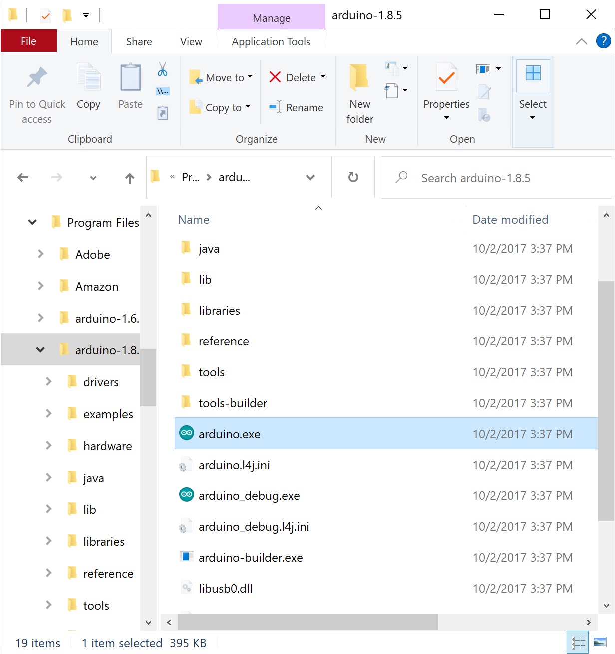
Note: Depending on your method of installing the Arduino IDE, the application may be on your desktop or the program folder.
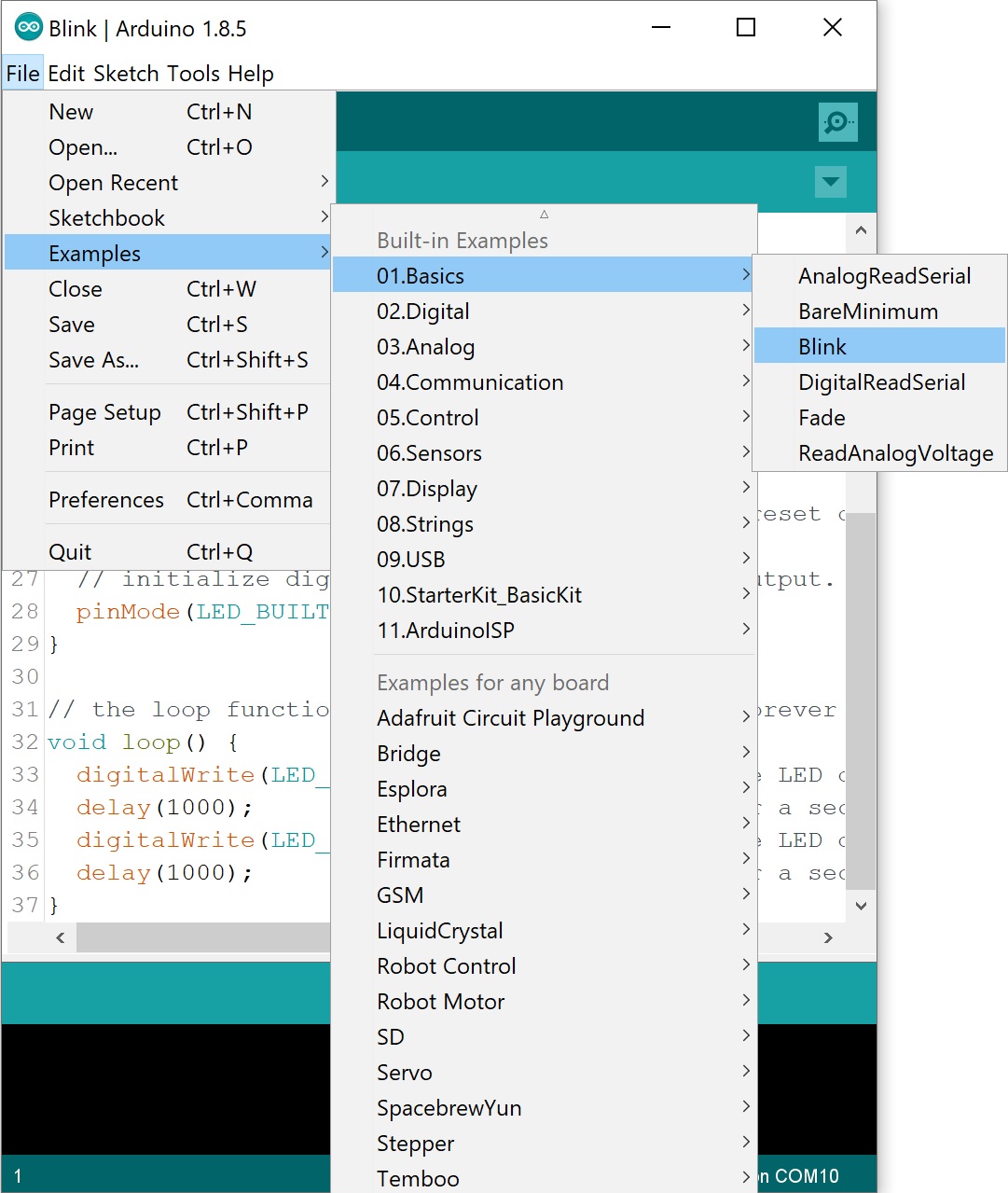
Open the Blink example sketch by going to: File > Examples > 01.Basics > Blink.
Select the type of Arduino board you’re using: Tools > Board > Arduino Uno.
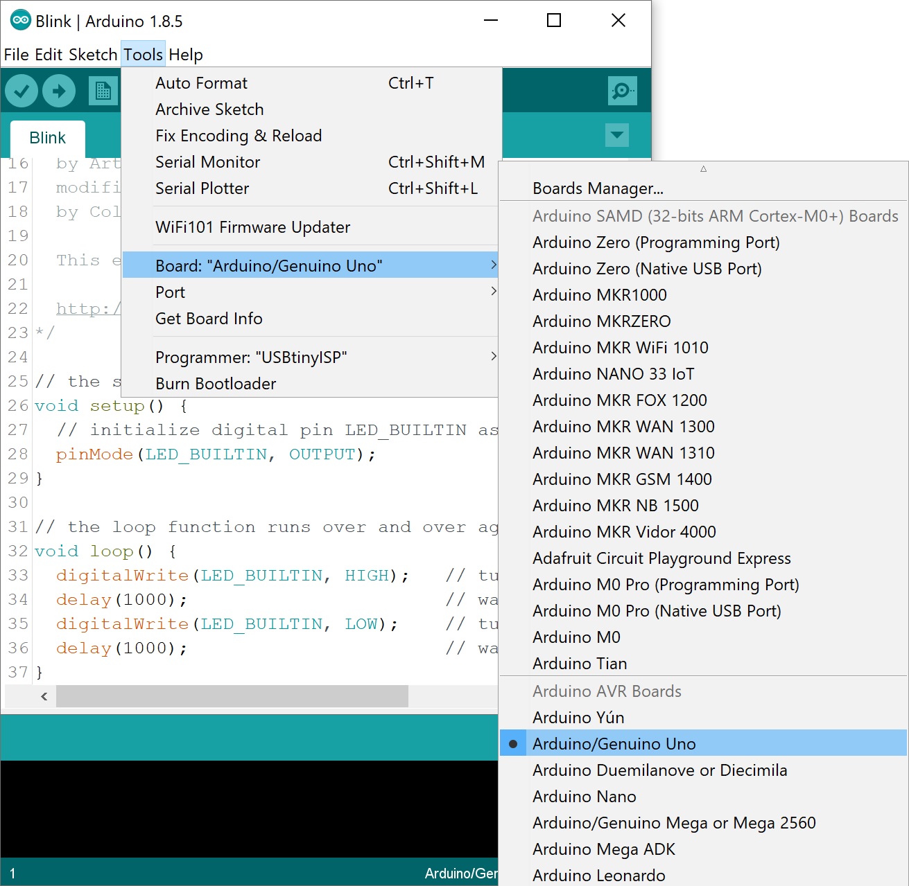
Note: As you move to other architectures, you may need to select a different board definition depending on your development board. For the Arduino Uno R3 and RedBoard development boards with ATmega328P, you can simply select Arduino Uno. Certain Arduino IDE versions may have you select Arduino/ Genuino Uno.
Select the serial/COM port that your Arduino is attached to: Tools > Port > COMxx. In this case it was COM11.
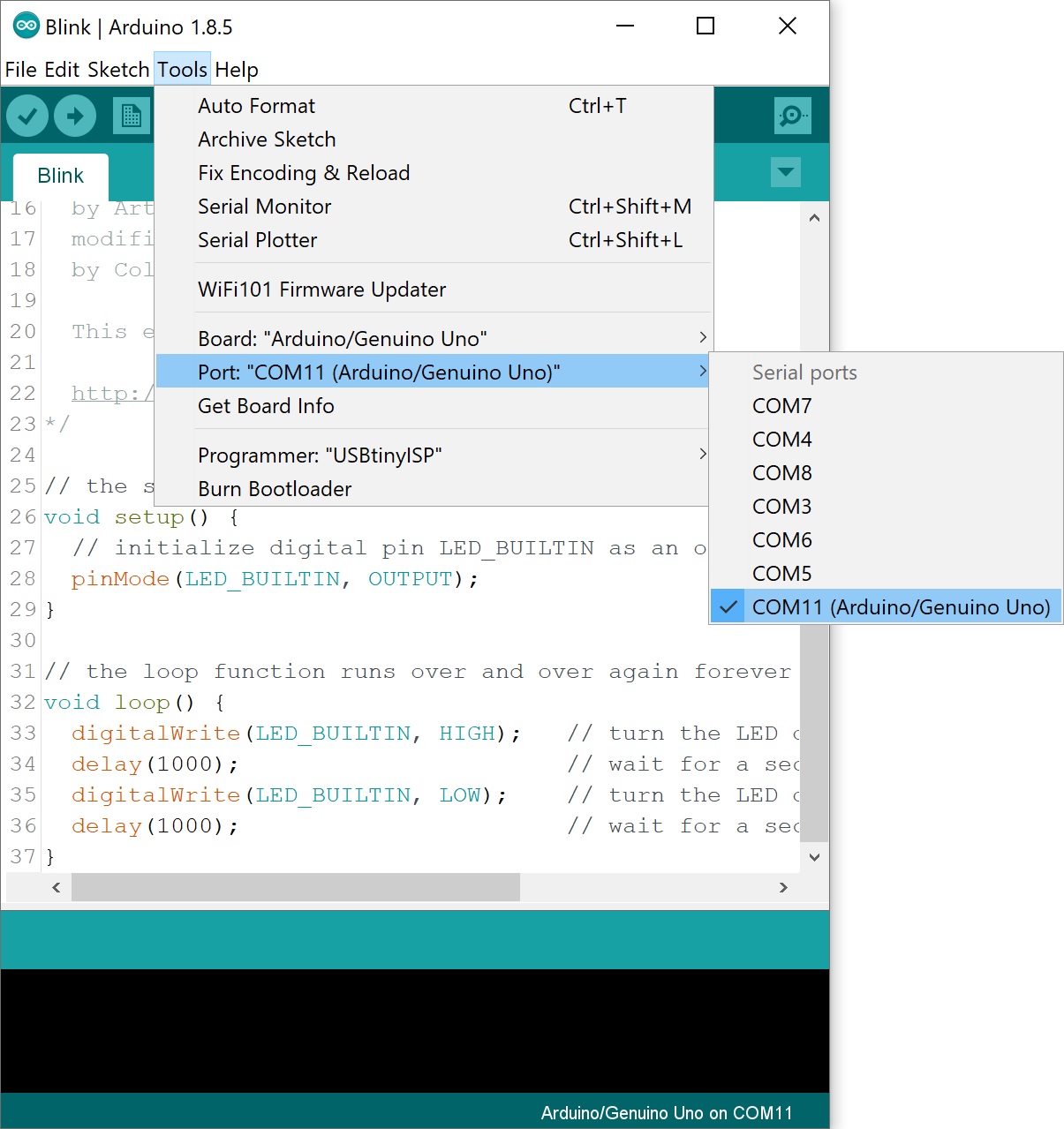
Note: If you’re not sure which serial device is your Arduino, take a look at the available ports, then unplug your Arduino and look again. The one that disappeared is your Arduino.
With your Arduino board connected, and the Blink sketch open, press the “Upload” button.

After a second, you should see some LEDs flashing on your Arduino, followed by the message “Done Uploading” in the status bar of the Blink sketch.

If everything worked, the onboard LED on your Arduino should now be blinking! You just programmed your first Arduino!
Note: Depending on the architecture and development board, the built-in LED may be defined on a different pin. You may need to adjust LED_BUILTIN or pin 13 to a different value before uploading.
Arduino EEPROM Explained
When you define and use a variable, the generated data within a sketch only lasts as long as the Arduino is on. If you reset or power off the Arduino, the data stored disappears.
If you want to keep the data stored for future use you need to use the Arduino EEPROM. This stores the variable’s data even when the Arduino resets or the power is turned off.
What is EEPROM?
The microcontroller on the Arduino board (ATMEGA328 in case of Arduino UNO, shown in figure below) has EEPROM (Electrically Erasable Programmable Read-Only Memory). This is a small space that can store byte variables.
The variables stored in the EEPROM kept there, event when you reset or power off the Arduino. Simply, the EEPROM is permanent storage similar to a hard drive in computers.

The EEPROM can be read, erased and re-written electronically. In Arduino, you can read and write from the EEPROM easily using the EEPROM library.
How many bytes can you store?
Each EEPROM position can save one byte, which means you can only store 8-bit numbers, which includes integer values between 0 and 255.
The bytes you can store on EEPROM dependson the microcontrollers on the Arduino boards. Take a look at the table below:
| Microcontroller | EEPROM |
| ATmega328 (Arduino Uno, Nano, Mini) | 1024 bytes |
| ATmega168 (Arduino Nano) | 512 bytes |
| ATmega2560 (Arduino Mega) | 4096 bytes |
However, if you need to store more data you can get an external EEPROM.
The EEPROM finite life
The EEPROM has a finite life. In Arduino, the EEPROM is specified to handle 100 000 write/erase cycles for each position. However, reads are unlimited. This means you can read from the EEPROM as many times as you want without compromising its life expectancy.
The EEPROM is useful in Arduino projects that need to keep data even when the Arduino resets or when power is removed. It is specially useful to remember the last state of a variable or to remember how many times an appliance was activated.
For example, imagine the following scenario:
- You’re controlling a lamp with your Arduino and the lamp is on;
- The Arduino suddenly loses power;
- When the power backs on, the lamp stays off – it doesn’t keep its last change.
You don’t want this to happen. You want the Arduino to remember what was happening before losing power and return to the last state.

To solve this problem, you can save the lamp’s state in the EEPROM and add a condition to your sketch to initially check whether the state of the lamp corresponds to the state previously saved in the EEPROM.
We’ll exemplify this with an example later in this post in the Example: Arduino EEPROM remember stored LED state.