Welcome, Developers & Engineers! We’re excited to have you here. This space is built for creators, problem-solvers, and tech enthusiasts like you. Whether you’re exploring projects, diving into code, or just visiting a site that speaks your language, you’re in the right place. In this blog, you will gain insightful knowledge of the MAX6675 Thermocouple Temperature Sensor Module. Moreover, understanding the basics of the MAX6675 can greatly enhance your high-temperature measurement projects. So, let’s get started.
What is MAX6675 Thermocouple Temperature Sensor Module?
The MAX6675 is a dedicated cold-junction compensated thermocouple-to-digital converter module that works exclusively with K-type thermocouples. Consequently, it is widely used in electronics projects for accurate temperature measurement in harsh or high-temperature environments (up to 1024°C). Manufactured by Maxim Integrated, this module performs cold-junction compensation and digitizes the thermocouple signal internally. Therefore, it provides a simple SPI interface, making it easy to connect with microcontrollers like Arduino, ESP32, or Raspberry Pi. Additionally, it includes built-in thermocouple break detection.
Working Principles of MAX6675 Temperature Sensor Module?
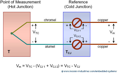
Thermocouple Operation: First, a K-type thermocouple generates a small voltage (Seebeck effect) based on the temperature difference between the hot junction (measurement point) and cold junction (module terminals).
Cold-Junction Compensation: Moreover, the MAX6675 measures the cold-junction temperature internally and compensates for it. As a result, the output represents the true hot-junction temperature.
Conversion and Output: In addition, the integrated 12-bit ADC converts the compensated signal to a digital value with 0.25°C resolution. Consequently, it outputs temperature data via SPI along with open thermocouple detection.
Hardware Overview of MAX6675 Temperature Sensor Module?
Communication: Furthermore, SPI protocol allows reading 16 bits of data (12-bit temperature + flags) in about 0.22 seconds per conversion.
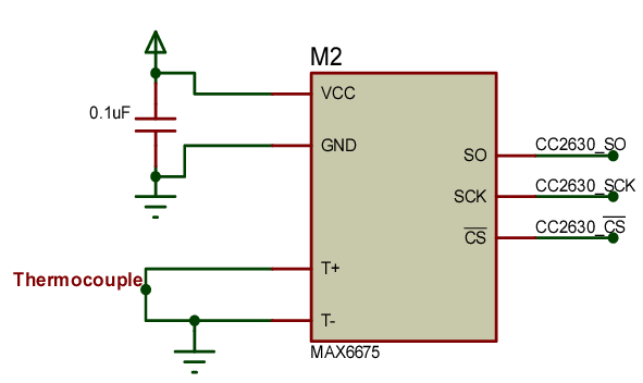
Supporting Circuitry: Additionally, includes filtering and cold-junction sensor on-chip. Consequently, no external components are needed beyond the thermocouple.
Technical Specifications of MAX6675 Temperature Sensor Module?
- Function: K-type thermocouple to digital converter with cold-junction compensation.
- Thermocouple Type: K-type only.
- Temperature Range: 0°C to +1024°C.
- Resolution: 0.25°C.
- Accuracy: ±8 LSB (typically ±2°C).
- Conversion Time: ~220 ms.
- Communication: SPI (3-wire).
- Operating Voltage: 3.0V to 5.5V.
- Current Consumption: ~1.5 mA.
- Features: Open thermocouple detection.
- Pinout: VCC, GND, SCK, CS, SO.
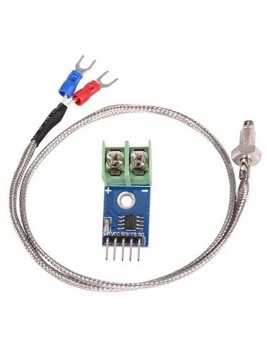
MAX6675 Temperature Sensor Module Pinout?
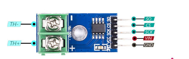
- VCC: Power supply (3.3V-5V)
- GND: Ground
- SCK: SPI clock
- CS: Chip select
- SO: Serial data out (MISO)
- Thermocouple + / -: K-type probe connections
Basic Connections to Arduino:
- VCC: Connect to 5V or 3.3V
- GND: Connect to Arduino GND
- SCK: Connect to pin 13 (SCK on Uno)
- CS: Connect to any digital pin (e.g., 10)
- SO: Connect to pin 12 (MISO)
Real Life Uses and Applications of MAX6675 Temperature Sensor Module?
The MAX6675 excels in extreme temperature environments where other sensors fail.
- Reflow Ovens: Precise control of soldering temperatures.
- Kilns and Furnaces: Monitors high-temperature firing processes.
- Exhaust Gas Monitoring: Measures engine or chimney temperatures.
- 3D Printer Hotends: High-temperature filament extrusion control.
- Industrial Heaters: Safety monitoring in manufacturing.
- BBQ/Smokers: Accurate meat or chamber temperature tracking.
- Scientific Experiments: High-heat reaction monitoring.
Using MAX6675 Temperature Sensor Module with Arduino
In this part, we will learn how you can use MAX6675 with Arduino Uno, Nano, or Mega to read high temperatures in just a few minutes – even if you’re a beginner.
What You Need:
- Any Arduino board (Uno recommended)
- MAX6675 Module
- K-type Thermocouple Probe
- Jumper wires
Wiring Diagram:
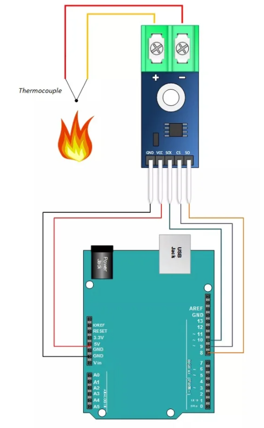
Use hardware SPI pins for best performance.
Code:
Install “MAX6675 library” by Adafruit via Arduino IDE Library Manager before uploading. Here’s a tested simple code – just copy-paste into your Arduino IDE.
#include <max6675.h>

int ktcSO =   8;   // MISO
int ktcCS =   9;
int ktcCLK = 10;  // SCK

MAX6675 ktc(ktcCLK, ktcCS, ktcSO);

void setup() {
  Serial.begin(9600);
  Serial.println("MAX6675 Thermocouple Sensor Ready!");
  delay(500);  // Wait for MAX chip to stabilize
}

void loop() {
  float temp = ktc.readCelsius();

  if (isnan(temp)) {
    Serial.println("Thermocouple error! Check connection.");
  } else
    Serial.print("C = ");
    Serial.println(temp);
  }

  delay(1000);  // Read every second
}
Credit: This example code is adapted from the official examples in the Adafruit MAX6675 library. Library available here: https://github.com/adafruit/MAX6675-library
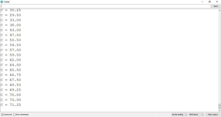
After uploading, open Serial Monitor (9600 baud). You’ll see accurate temperature readings from your K-type probe updating every second!
Note: Connect thermocouple with correct polarity (+ yellow, – red for standard K-type). Allow 500ms warm-up. Moreover, keep module away from heat source for accurate cold-junction compensation.
Wrapping up
In this post, we’ve covered all the fundamental aspects of the MAX6675 Thermocouple Temperature Sensor Module. We trust that the information provided has been clear and insightful. Feel free to ask any questions you may have about this topic in the comment section below. We are here to help and provide additional clarification as needed.