What is MAX30102 Pulse Oximetry and Heart Rate Monitoring Sensor? & How Does It Work?
Welcome, Developers & Engineers!We’re excited to have you here. This space is built for creators, problem-solvers, and tech enthusiasts like you. Whether you’re exploring projects, diving into code, or just visiting a site that speaks your language, you’re in the right place. In this blog, you will gain insightful knowledge of the MAX30102 Sensor Module. Moreover, understanding the basics of the MAX30102 can greatly enhance your health monitoring and wearable projects. So, let’s get started.
What is MAX30102 Sensor Module?
The MAX30102 is a high-sensitivity optical sensor module for pulse oximetry and heart rate monitoring. Consequently, it is widely used in DIY wearable devices to measure heart rate (BPM) and blood oxygen saturation (SpO2). Manufactured by Maxim Integrated (now Analog Devices), this module integrates red and infrared LEDs with a photodetector. Therefore, it uses I2C communication, making it easy to interface with microcontrollers like Arduino, ESP32, or Raspberry Pi. Additionally, breakout boards usually include a 3.3V regulator and level shifters for 5V compatibility.
Working Principles of MAX30102 Sensor Module?
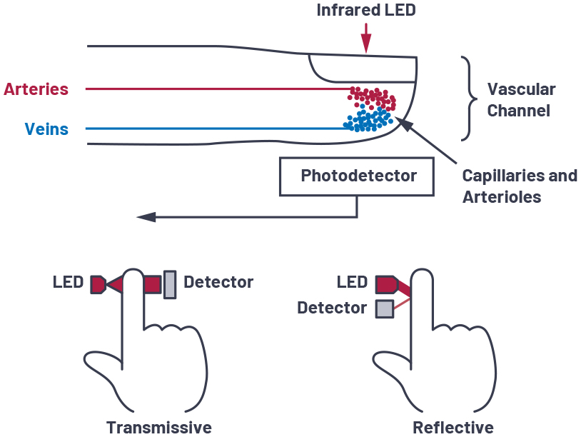
Photoplethysmography (PPG): First, the module emits red (660 nm) and infrared (880 nm) light through the skin using its LEDs. As a result, some light is absorbed by blood, and the rest is reflected back to the photodetector.
Heart Rate Detection: Moreover, blood volume changes with each heartbeat (pulsatile flow). Consequently, the detected light intensity varies at the heart rate frequency, allowing BPM calculation from peak intervals.
SpO2 Calculation: In addition, oxygenated and deoxygenated hemoglobin absorb red and IR light differently. Therefore, the ratio of AC/DC components from both wavelengths is used to estimate oxygen saturation (SpO2).
Digital Processing: Furthermore, the on-chip ADC and digital filters provide clean data via I2C registers.
Hardware Overview of MAX30102 Sensor Module?
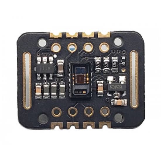
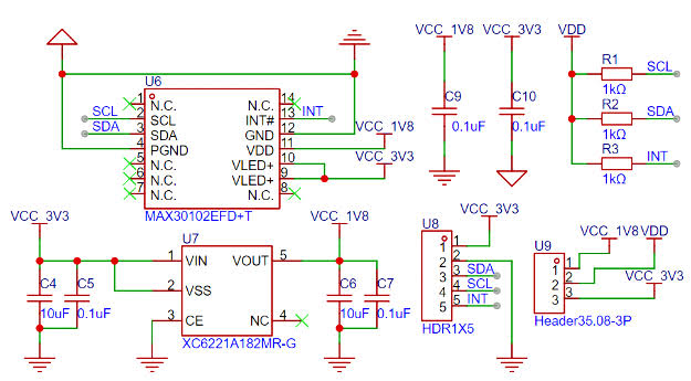
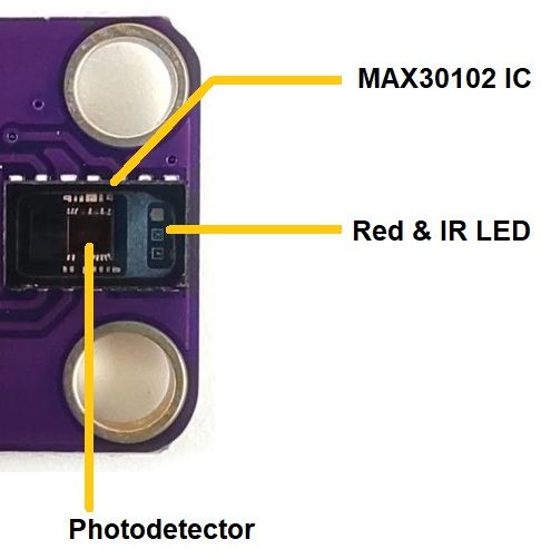
The MAX30102 module is a small breakout board with the MAX30102 IC, red/IR LEDs, photodetector, and supporting circuitry.
The sensor is designed for finger placement (transmission mode) or wrist/forehead (reflection mode). As a result, proper contact and minimal motion are crucial for accurate readings.
Supporting Circuitry: Additionally, modules include a voltage regulator (3.3V operation) and I2C pull-up resistors.
Consequently, connection is simple – just power and I2C lines.
Technical Specifications of MAX30102 Sensor Module?
- Function: Optical heart rate and SpO2 monitoring.
- LED Wavelengths: Red 660 nm, Infrared 880 nm.
- Output: Digital I2C (address 0x57).
- Sampling Rate: Up to 3200 samples/sec.
- Resolution: 18-bit ADC.
- Operating Voltage: 3.3V to 5V (module), chip 1.8V-3.3V.
- Current Consumption: ~600 µA average, up to 50 mA peak (LEDs).
- Heart Rate Range: 30-240 BPM (typical).
- SpO2 Range: 70-100% (clinical accuracy requires calibration).
- Pinout: VCC, GND, SCL, SDA, INT (interrupt), optional others.
MAX30102 Sensor Module Pinout?
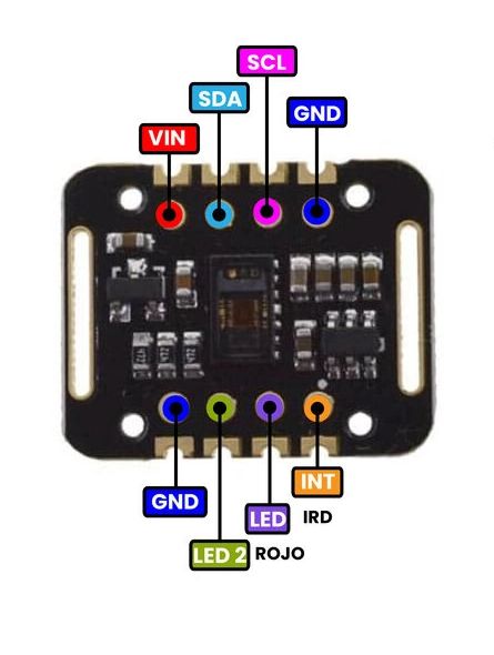
- VCC: Power supply (3.3V-5V)
- GND: Ground
- SCL: I2C clock (A5 on Uno)
- SDA: I2C data (A4 on Uno)
- INT: Interrupt output (optional, for FIFO ready)
Basic Connections to Arduino:
- VCC: Connect to 3.3V or 5V on Arduino
- GND: Connect to Arduino GND
- SCL: Connect to A5 (Uno) or SCL pin
- SDA: Connect to A4 (Uno) or SDA pin
Real Life Uses and Applications of MAX30102 Sensor Module?
The MAX30102 is popular for non-medical health tracking and fitness projects.
- Wearable Fitness Trackers: Monitors heart rate during exercise.
- Pulse Oximeters: DIY devices to check blood oxygen levels.
- Sleep Trackers: Detects heart rate variability overnight.
- Stress Monitors: Uses HRV for relaxation feedback.
- Smart Mirrors: Displays vital signs in bathroom mirrors.
- Remote Health Monitoring: Sends data to apps for elderly care.
- Biofeedback Games: Controls games with heart rate.
Using MAX30102 Sensor Module with Arduino
In this part, we will learn how you can use MAX30102 with Arduino Uno, Nano, or Mega to measure heart rate and SpO2 in just a few minutes – even if you’re a beginner.
What You Need:
- Any Arduino board (Uno recommended)
- MAX30102 Sensor Module
- Jumper wires
- Breadboard (optional)
Wiring Diagram:
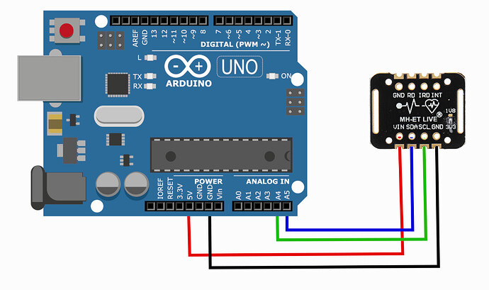
Connect via I2C – no extra components needed.
Code:
Install “SparkFun MAX3010x Sensor Library” (supports MAX30102) via Arduino IDE Library Manager before uploading. Here’s a tested simple code – just copy-paste into your Arduino IDE.
#include <Wire.h>
#include "MAX30105.h"  // SparkFun library (works for MAX30102)
#include "heartRate.h"

MAX30105 particleSensor;

const byte RATE_SIZE = 4;
byte rates[RATE_SIZE];
byte rateSpot = 0;
long lastBeat = 0;
float beatsPerMinute;
int beatAvg;

void setup() {
  Serial.begin(115200);
  Serial.println("MAX30102 Heart Rate Monitor Ready!");

  if (!particleSensor.begin(Wire, I2C_SPEED_FAST)) {
    Serial.println("MAX30102 not found!");
    while (1);
  }

  particleSensor.setup(); // Default settings
  particleSensor.setPulseAmplitudeRed(0x0A); // Low brightness to save power
  particleSensor.setPulseAmplitudeIR(0x0A);
}

void loop() {
  long irValue = particleSensor.getIR();

  if (checkForBeat(irValue) == true) {
    long delta = millis() - lastBeat;
    lastBeat = millis();

    beatsPerMinute = 60 / (delta / 1000.0);

    if (beatsPerMinute < 255 && beatsPerMinute > 20) {
      rates[rateSpot++] = (byte)beatsPerMinute;
      rateSpot %= RATE_SIZE;

      beatAvg = 0;
      for (byte x = 0; x < RATE_SIZE; x++) beatAvg += rates[x];
      beatAvg /= RATE_SIZE;
    }
  }

  Serial.print("IR=");
  Serial.print(irValue);
  Serial.print(", BPM=");
  Serial.print(beatsPerMinute);
  Serial.print(", Avg BPM=");
  Serial.println(beatAvg);

  if (irValue < 50000) Serial.println("No finger detected!");
}
Credit: This example code is adapted from the official examples in the SparkFun MAX3010x library (compatible with MAX30102). Library available here: https://github.com/sparkfun/SparkFun_MAX3010x_Sensor_Library
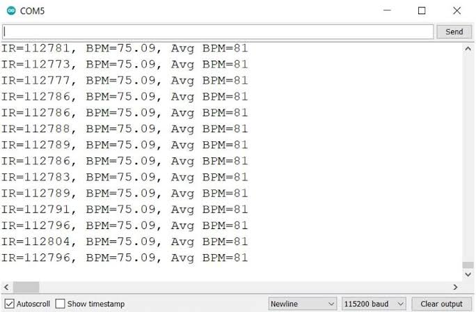
After uploading, place your finger gently on the sensor. Open Serial Monitor (115200 baud) – after a few seconds, you’ll see stable BPM and average heart rate. Keep finger still for best accuracy!
Note: SpO2 calculation requires more advanced processing (see library examples). Readings are for educational use only – not medical grade. Moreover, good skin contact and ambient light shielding improve results.
Wrapping up
In this post, we’ve covered all the fundamental aspects of the MAX30102 Sensor Module. We trust that the information provided has been clear and insightful. Feel free to ask any questions you may have about this topic in the comment section below. We are here to help and provide additional clarification as needed.