What is HMC5883L Magnetometer Sensor & How does it work ?
Welcome, Developers & Engineers! We’re excited to have you here. This space is built for creators, problem-solvers, and tech enthusiasts like you. Whether you’re exploring projects, diving into code, or just visiting a site that speaks your language, you’re in the right place. In this blog, you will gain insightful knowledge of the HMC5883L Sensor Module. Moreover, understanding the basics of the HMC5883L can greatly enhance your orientation and navigation projects. So, let’s get started.
What is HMC5883L Sensor Module?
The HMC5883L is a popular 3-axis digital magnetometer module that measures magnetic fields along X, Y, and Z axes. As a result, it is widely used in electronics projects to detect the Earth’s magnetic field, determine compass heading, and enable navigation features. Manufactured by Honeywell, this sensor communicates via I2C protocol. Therefore, it is very easy to interface with microcontrollers such as Arduino, ESP32, or Raspberry Pi. Additionally, many breakout boards (commonly known as GY-273) include a voltage regulator and pull-up resistors for simple connection.
Working Principles of HMC5883L Sensor Module?
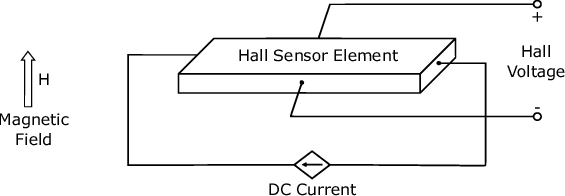
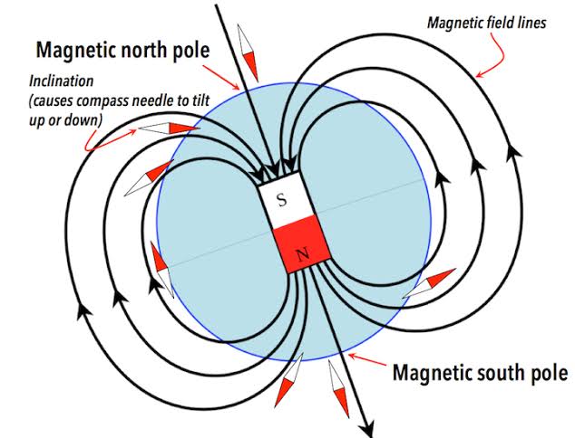
Magnetic Field Measurement: First, the HMC5883L uses magneto-resistive sensors based on Anisotropic Magneto-Resistive (AMR) technology. These sensors change their resistance when exposed to a magnetic field. Consequently, when the Earth’s magnetic field (or any external field) acts on the sensor, the resistance of thin permalloy strips changes. This change is then converted into voltage differences, which are further amplified and digitized by an internal 12-bit ADC. As a result, the module provides magnetic field strength in three axes, typically in units of milliGauss (mG) or microTesla (µT).
Compass Heading Calculation: Moreover, by measuring the X and Y axis values, you can calculate the heading angle using the arctangent function (atan2). However, to get accurate compass readings, tilt compensation is often required when combined with an accelerometer. Therefore, the HMC5883L is frequently paired with accelerometers (like in the MPU6050) for better orientation results.
Digital Communication: In addition, the sensor uses I2C protocol with a default address of 0x1E. Data is stored in registers, and readings are obtained by requesting the X, Y, and Z axis data registers. Furthermore, the module supports continuous measurement mode or single measurement mode for power saving.
Hardware Overview of HMC5883L Sensor Module?
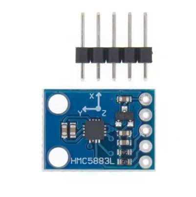
The HMC5883L module is a compact breakout board (usually GY-273) that includes the HMC5883L chip, a 3.3V regulator, I2C pull-up resistors, and decoupling capacitors.
The core chip is a surface-mount device with integrated AMR sensors and signal processing circuitry. As a result, most modules provide 5 pins for easy interfacing.
Supporting Circuitry: Additionally, modules typically include a low-dropout regulator to accept 3-5V input while the chip operates at 3.3V. Pull-up resistors on SDA and SCL ensure stable I2C communication.
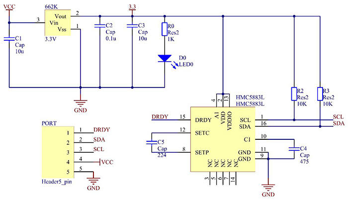
Consequently, no extra components are needed beyond power and I2C lines. However, keep the sensor away from strong magnetic interference for accurate readings.
Technical Specifications of HMC5883L Sensor Module?
- Function: 3-axis digital compass/magnetometer.
- Output: Digital I2C interface, 12-bit resolution.
- Sensor Type: Anisotropic Magneto-Resistive (AMR).
- Field Range: ±0.88 to ±8.1 Gauss (programmable gain).
- Pinout: 5 pins (VCC, GND, SCL, SDA, DRDY – optional).
- Communication: I2C, address 0x1E.
- Measurement Specifications: Resolution up to 2 milliGauss, ±1° heading accuracy after calibration.
- Operating Voltage: 3V to 5V (module), chip 2.16V-3.6V.
- Current Consumption: ~100µA in continuous mode, very low power.
- Data Output Rate: 0.75 Hz to 75 Hz (configurable).
- Data Format: 16-bit signed values for X, Y, Z axes.
HMC5883L Sensor Module Pinout?
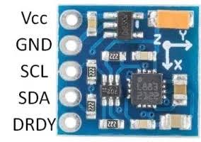
- VCC: Power supply (3-5V)
- GND: Ground
- SCL: I2C clock line (connect to Arduino A5 or SCL pin)
- SDA: I2C data line (connect to Arduino A4 or SDA pin)
- DRDY: Data Ready interrupt (optional, not used in basic examples)
Basic Connections to Arduino:
- VCC: Connect to 5V or 3.3V on Arduino
- GND: Connect to Arduino GND
- SCL: Connect to A5 (Uno) or SCL pin
- SDA: Connect to A4 (Uno) or SDA pin
Real Life Uses and Applications of HMC5883L Sensor Module?
The HMC5883L is a low-cost, reliable 3-axis magnetometer perfect for hobbyist, educational, and navigation-related projects.
- Digital Compass: Builds simple electronic compasses that show North direction on LCD or OLED displays.
- Robot Navigation: Helps robots maintain heading or return home in outdoor environments.
- Drone Orientation: Provides yaw axis data when combined with gyro and accelerometer for stable flight.
- Metal Detectors: Detects nearby ferromagnetic materials or buried objects.
- Augmented Reality Devices: Tracks device orientation relative to Earth’s magnetic field.
- Weather Stations: Adds wind direction sensing when attached to a vane.
- Vehicle Tracking: Monitors direction in GPS-dead zones for dead reckoning.
Using HMC5883L Sensor Module with Arduino
In this part, we will learn how you can use HMC5883L with Arduino Uno, Nano, or Mega to read magnetic field values and calculate heading in just a few minutes – even if you’re a beginner.
What You Need:
- Any Arduino board (Uno recommended)
- HMC5883L module (GY-273)
- Jumper wires
- Breadboard (optional)
Wiring Diagram:
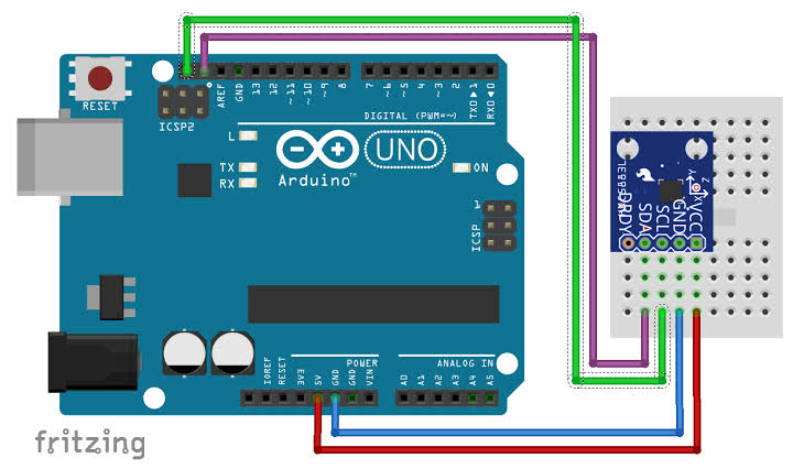
Connect directly via I2C – no extra resistors needed as they’re on the module.
Code:
Install “Adafruit HMC5883 Unified” and “Adafruit Sensor” libraries via Arduino IDE Library Manager before uploading. Here’s a tested simple code – just copy-paste into your Arduino IDE.
#include <Wire.h>
#include <Adafruit_Sensor.h>
#include <Adafruit_HMC5883_U.h>

/* Assign a unique ID to this sensor */
Adafruit_HMC5883_Unified mag = Adafruit_HMC5883_Unified(12345);

void setup(void) {
  Serial.begin(9600);

  if(!mag.begin()) {
    Serial.println("Failed to find HMC5883L chip!");
    while(1) { delay(10); }
  }

  Serial.println("HMC5883L Found!");

  // Display some basic information
  sensor_t sensor;
  mag.getSensor(&sensor);
  Serial.println("Sensor: HMC5883L");
}

void loop(void) {
  /* Get a new sensor event */
  sensors_event_t event;
  mag.getEvent(&event);

  // Display the results (magnetic field is in microTesla)
  Serial.print("X: "); Serial.print(event.magnetic.x);
  Serial.print("  Y: "); Serial.print(event.magnetic.y);
  Serial.print("  Z: "); Serial.print(event.magnetic.z);
  Serial.println(" uT");

  // Calculate heading (in degrees)
  float heading = atan2(event.magnetic.y, event.magnetic.x);

  // Convert to 0-360 degrees
  if(heading < 0) heading += 2*PI;

  float headingDegrees = heading * 180 / PI;

  Serial.print("Heading: ");
  Serial.print(headingDegrees);
  Serial.println(" degrees");

  Serial.println("");
  delay(2000);
}
Credit: This example code is adapted from the official examples in the Adafruit HMC5883 Unified library by Adafruit Industries. Library available here: https://github.com/adafruit/Adafruit_HMC5883_Unified
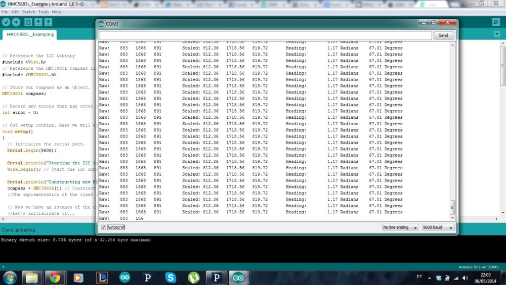
After uploading the code, open the Serial Monitor (Ctrl+Shift+M), set baud rate to 9600, and you’ll see live magnetic field values in µT and calculated heading in degrees updating every 2 seconds. Rotate the sensor horizontally to see the heading change!
Note: For accurate compass readings, perform calibration by rotating the sensor in a figure-8 pattern. Moreover, avoid placing it near magnets, motors, or metal objects. For advanced use, combine with an accelerometer for tilt-compensated heading.
Wrapping up
In this post, we’ve covered all the fundamental aspects of the HMC5883L Sensor Module. We trust that the information provided has been clear and insightful. Feel free to ask any questions you may have about this topic in the comment section below. We are here to help and provide additional clarification as needed.