What is ADXL345 Accelerometer Sensor ? & How does it work ?
Welcome, Developers & Engineers! We’re excited to have you here. This space is built for creators, problem-solvers, and tech enthusiasts like you. Whether you’re exploring projects, diving into code, or just visiting a site that speaks your language, you’re in the right place. In this blog, you will gain insightful knowledge of the ADXL345 Sensor Module. Moreover, understanding the basics of the ADXL345 can greatly enhance your motion and tilt-sensing projects. So, let’s get started.
What is ADXL345 Sensor Module?
The ADXL345 is a popular 3-axis digital accelerometer module that measures linear acceleration along X, Y, and Z axes. Consequently, it is widely used in electronics projects to detect motion, tilt, vibration, and shock. Manufactured by Analog Devices, this sensor supports both I2C and SPI protocols. Therefore, it is very easy to interface with microcontrollers such as Arduino, ESP32, or Raspberry Pi. Additionally, common breakout boards (like GY-291) include a voltage regulator and level shifters for simple 3-5V operation.
Working Principles of ADXL345 Sensor Module?
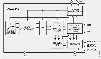
Acceleration Measurement: First, the ADXL345 uses MEMS (Micro-Electro-Mechanical Systems) capacitive technology. It detects changes in capacitance caused by the deflection of a polysilicon proof mass suspended over etched plates. When acceleration is applied, the mass moves, which in turn alters the capacitance. As a result, this change is converted to a voltage, amplified, and digitized by a 13-bit ADC, providing high-resolution measurements up to ±16g.
Digital Communication: In addition, the sensor supports I2C (default address 0x53) or SPI communication. Data is stored in registers as 16-bit two’s complement values. Moreover, built-in features like FIFO buffer, tap detection, and free-fall interrupts reduce microcontroller load.
Hardware Overview of ADXL345 Sensor Module?
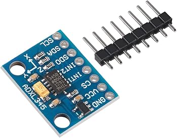
The ADXL345 module is a compact breakout board (commonly GY-291) that includes the ADXL345 chip, a 3.3V regulator, level shifters for I2C/SPI, and decoupling capacitors.
The core chip is a small LGA package with integrated sensing elements and signal processing. As a result, modules typically have 7-8 pins for easy connection.
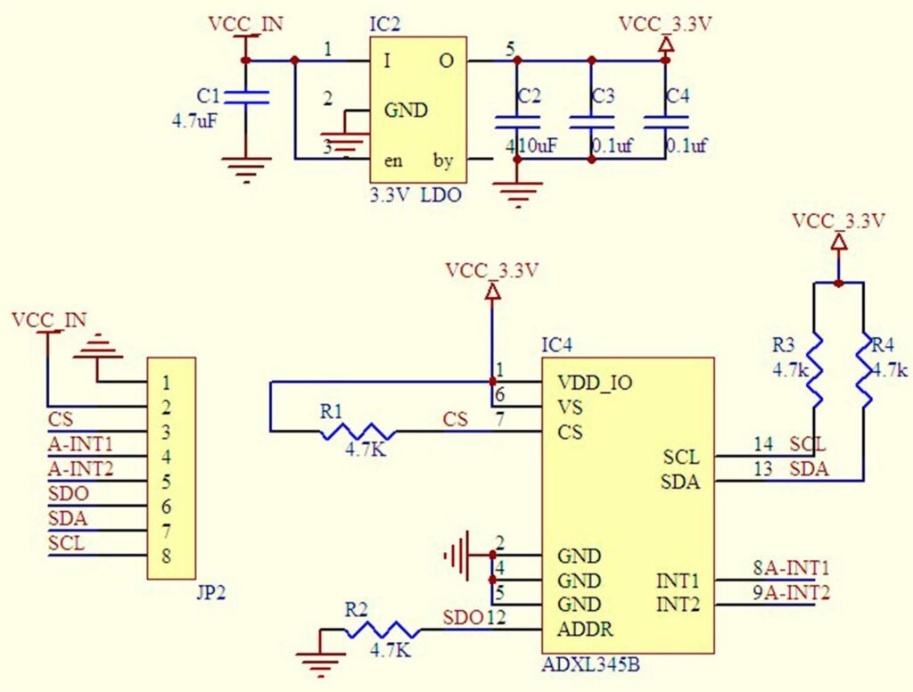
Supporting Circuitry: Most modules feature a low-dropout regulator for 3-5V input and pull-up resistors on I2C lines. Additionally, some include CS pin for protocol selection. Consequently, no extra components are usually needed. However, keep the sensor away from strong vibrations or magnetic fields during calibration for best accuracy.
Technical Specifications of ADXL345 Sensor Module?
- Function: 3-axis digital accelerometer with advanced features.
- Output: Digital I2C/SPI interface, up to 13-bit resolution.
- Sensor Type: MEMS capacitive.
- Measurement Range: ±2g, ±4g, ±8g, ±16g (programmable).
- Pinout: VCC, GND, SCL, SDA, SDO, CS, INT1/INT2.
- Communication: I2C (address 0x53) or SPI.
- Resolution: Up to 3.9 mg/LSB (±2g range).
- Data Rate: 0.1 Hz to 3200 Hz.
- Operating Voltage: 3V to 5V (module), chip 2.0V-3.6V.
- Current Consumption: 40-145µA (measurement), ultra-low power.
- Additional Features: FIFO buffer, tap/double-tap, activity/inactivity, free-fall detection.
ADXL345 Sensor Module Pinout?
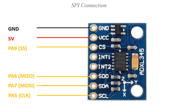
- VCC: Power supply (3-5V)
- GND: Ground
- SCL: I2C clock or SPI clock
- SDA: I2C data or SPI data in
- SDO: I2C address select / SPI data out
- CS: Chip select (for SPI mode)
- INT1/INT2: Interrupt outputs (optional)
Basic Connections to Arduino (I2C mode):
- VCC: Connect to 5V or 3.3V on Arduino
- GND: Connect to Arduino GND
- SCL: Connect to A5 (Uno) or SCL pin
- SDA: Connect to A4 (Uno) or SDA pin
Real Life Uses and Applications of ADXL345 Sensor Module?
The ADXL345 is a low-power, high-resolution 3-axis accelerometer perfect for hobbyist, educational, and industrial projects involving motion detection.
- Tilt Sensing Devices: Measures inclination for level detectors or screen orientation in phones.
- Vibration Monitoring: Detects machine vibrations for predictive maintenance.
- Impact/Shock Detection: Triggers airbags in vehicles or fall detection in wearables.
- Gesture Recognition: Enables hand motion control in gaming or remote devices.
- Robotics: Provides acceleration data for balance and navigation.
- Drop Detection: Monitors packages for rough handling during shipping.
- Activity Trackers: Counts steps or monitors movement in fitness devices.
Using ADXL345 Sensor Module with Arduino
In this part, we will learn how you can use ADXL345 with Arduino Uno, Nano, or Mega to read acceleration values in just a few minutes – even if you’re a beginner.
What You Need:
- Any Arduino board (Uno recommended)
- ADXL345 module (GY-291)
- Jumper wires
- Breadboard (optional)
Wiring Diagram:
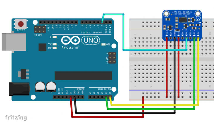
Connect directly via I2C – no extra resistors needed as they’re on the module.
Code:
Install “Adafruit ADXL345” and “Adafruit Unified Sensor” libraries via Arduino IDE Library Manager before uploading. Here’s a tested simple code – just copy-paste into your Arduino IDE.
#include <Wire.h>
#include <Adafruit_Sensor.h>
#include <Adafruit_ADXL345_U.h>

/* Assign a unique ID to this sensor */
Adafruit_ADXL345_Unified accel = Adafruit_ADXL345_Unified(12345);

void setup(void) {
  Serial.begin(9600);

  if(!accel.begin()) {
    Serial.println("Failed to find ADXL345 chip!");
    while(1) { delay(10); }
  }

  Serial.println("ADXL345 Found!");

  accel.setRange(ADXL345_RANGE_16_G);
}

void loop(void) {
  sensors_event_t event;
  accel.getEvent(&event);

  Serial.print("X: "); Serial.print(event.acceleration.x);
  Serial.print("  Y: "); Serial.print(event.acceleration.y);
  Serial.print("  Z: "); Serial.print(event.acceleration.z);
  Serial.println(" m/s^2");

  Serial.println("");
  delay(2000);
}
Credit: This example code is adapted from the official examples in the Adafruit ADXL345 library by Adafruit Industries. Library available here: https://github.com/adafruit/Adafruit_ADXL345
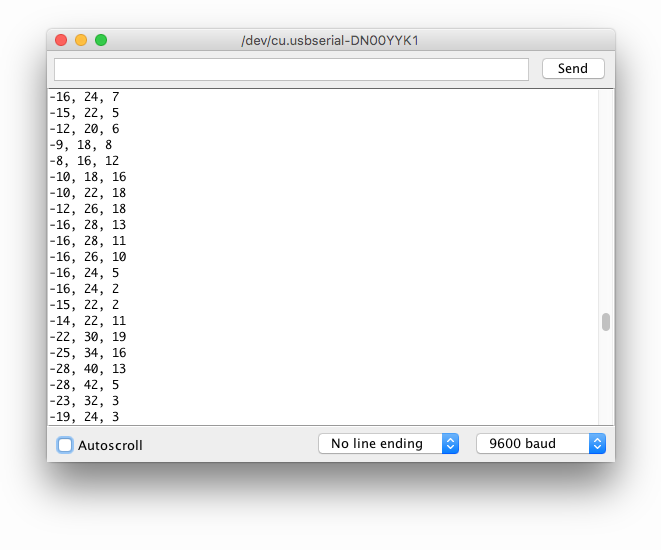
After uploading the code, open the Serial Monitor (Ctrl+Shift+M), set baud rate to 9600, and you’ll see live acceleration values in m/s² updating every 2 seconds. Tilt the sensor to see gravity shift between axes!
Note: For better accuracy, calibrate by placing the sensor flat (Z ≈ 9.8 m/s², X/Y ≈ 0). Moreover, avoid interference from motors or magnets. Advanced features like tap detection are available in the library examples.
Wrapping up
In this post, we’ve covered all the fundamental aspects of the ADXL345 Sensor Module. We trust that the information provided has been clear and insightful. Feel free to ask any questions you may have about this topic in the comment section below. We are here to help and provide additional clarification as needed.