What is ACS712 Current Sensor ? & How Does It Work?
Welcome, Developers & Engineers! We’re excited to have you here. This space is built for creators, problem-solvers, and tech enthusiasts like you. Whether you’re exploring projects, diving into code, or just visiting a site that speaks your language, you’re in the right place. In this blog, you will gain insightful knowledge of the ACS712 Current Sensor Module. Moreover, understanding the basics of the ACS712 can greatly enhance your power monitoring and safety projects. So, let’s get started.
What is ACS712 Current Sensor Module?
The ACS712 is a popular hall-effect-based linear current sensor module that measures both AC and DC current flowing through a wire. Consequently, it is widely used in Arduino and microcontroller projects for monitoring load current, over-current protection, and power consumption. Manufactured by Allegro Microsystems, this fully integrated sensor provides an analog voltage output proportional to the sensed current. Therefore, it is very easy to interface with microcontrollers like Arduino, ESP32, or Raspberry Pi via an ADC pin. Additionally, it offers galvanic isolation, making it safe for high-voltage applications.
Working Principles of ACS712 Current Sensor Module?
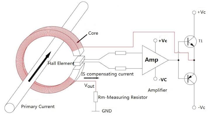
Hall Effect Sensing: First, current flowing through the integrated copper conduction path generates a magnetic field. As a result, the onboard hall-effect IC detects this field and converts it to a proportional voltage.
Output Voltage: Moreover, the sensor outputs a voltage centered at VCC/2 (2.5V for 5V supply) with a sensitivity depending on the model: ±185 mV/A (5A), ±100 mV/A (20A), or ±66 mV/A (30A). Consequently, positive current gives output above 2.5V, negative below.
Bidirectional Measurement: In addition, it measures both AC (as RMS after processing) and DC current without needing to break the circuit – just pass the wire through the hole or solder it to IP+ and IP- terminals.
Isolation: Furthermore, the low-resistance path provides electrical isolation up to 2.1 kV RMS.
Hardware Overview of ACS712 Current Sensor Module?
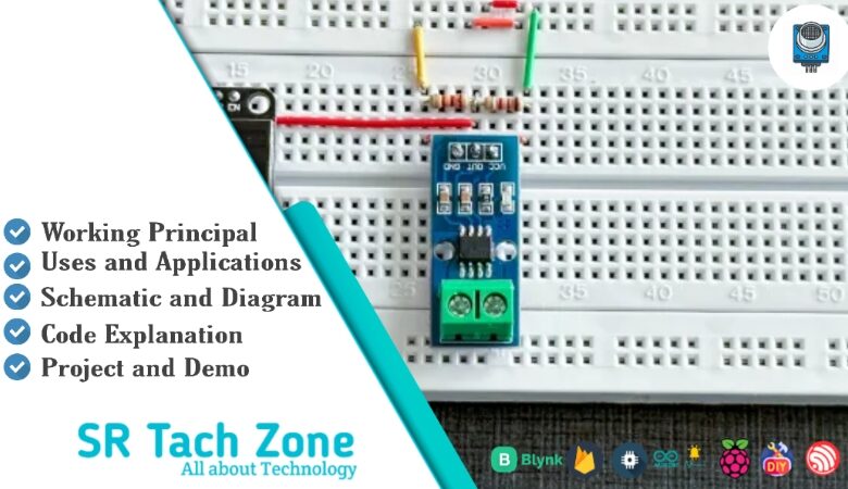
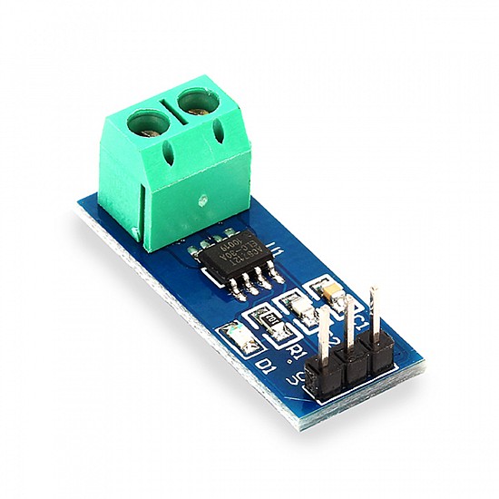
The ACS712 module is a small breakout board with the ACS712 IC, filter capacitor, and screw terminals or through-hole for current path.
The current path is a thick copper trace with IP+ and IP- pins. As a result, versions are labeled 5A, 20A, or 30A based on range.
Supporting Circuitry: Additionally, a 0.1µF filter capacitor reduces noise on the output pin. Consequently, wiring is simple – power, ground, and analog output.
Technical Specifications of ACS712 Current Sensor Module?
- Function: Non-invasive bidirectional AC/DC current sensing.
- Output: Analog voltage (ratiometric).
- Current Range: ±5A, ±20A, or ±30A (model dependent).
- Sensitivity: 185 mV/A (5A), 100 mV/A (20A), 66 mV/A (30A).
- Operating Voltage: 4.5V to 5.5V DC.
- Current Consumption: ~10 mA.
- Bandwidth: 80 kHz.
- Accuracy: ±1.5% at 25°C.
- Isolation Voltage: 2.1 kV RMS.
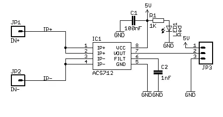
- Pinout: VCC, GND, OUT, IP+, IP- (current terminals).
ACS712 Current Sensor Module Pinout?
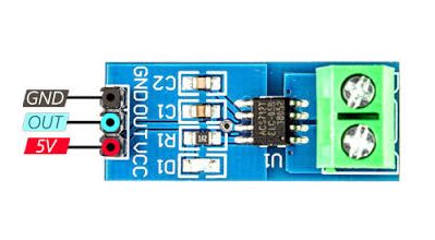
- VCC: Power supply (5V)
- GND: Ground
- OUT: Analog voltage output
- IP+ / IP-: Current input terminals (wire to be measured)
Basic Connections to Arduino:
- VCC: Connect to 5V on Arduino
- GND: Connect to Arduino GND
- OUT: Connect to analog pin (e.g., A0)
Real Life Uses and Applications of ACS712 Current Sensor Module?
The ACS712 is ideal for safe, accurate current monitoring in power systems.
- Power Monitoring: Measures appliance or solar panel current consumption.
- Over-Current Protection: Shuts down circuits when current exceeds safe limits.
- Battery Chargers: Monitors charging/discharging current.
- Motor Control: Detects load current in robots or pumps.
- Home Energy Meters: Tracks total power usage per device.
- Inverter Feedback: Provides current data for solar inverters.
- Smart Plugs: Adds current sensing to remote-controlled outlets.
Using ACS712 Current Sensor Module with Arduino
In this part, we will learn how you can use ACS712 (20A version example) with Arduino Uno, Nano, or Mega to measure current in just a few minutes – even if you’re a beginner.
What You Need:
- Any Arduino board (Uno recommended)
- ACS712 Current Sensor Module (5A/20A/30A)
- Jumper wires
- Load (e.g., bulb or motor with power supply)
Wiring Diagram:
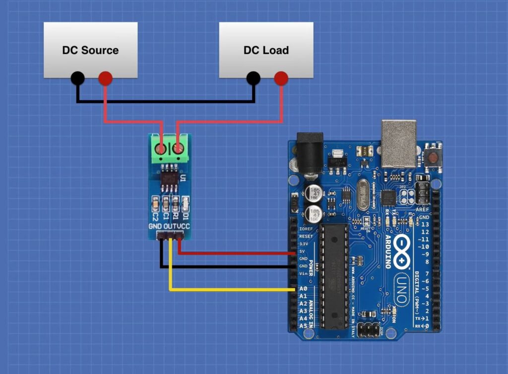
Connect the load in series with IP+ and IP- terminals.
Code:
No special library is required – just use analogRead(). Here’s a tested simple code for the 20A version – just copy-paste into your Arduino IDE.
#define CURRENT_PIN A0   // OUT to analog pin A0
float sensitivity = 0.100;  // 100 mV/A for 20A version (use 0.185 for 5A, 0.066 for 30A)
float offsetVoltage = 2.5;  // VCC/2

void setup() {
  Serial.begin(9600);
  Serial.println("ACS712 Current Sensor Ready!");
}

void loop() {
  int rawValue = analogRead(CURRENT_PIN);
  float voltage = (rawValue / 1023.0) * 5.0;  // Convert to voltage
  float current = (voltage - offsetVoltage) / sensitivity;

  Serial.print("Raw: ");
  Serial.print(rawValue);
  Serial.print(" | Voltage: ");
  Serial.print(voltage);
  Serial.print("V | Current: ");
  Serial.print(abs(current));  // Use abs() for magnitude
  Serial.println("A");

  delay(500);
}
Note: This is a basic example using standard Arduino functions – no external library needed.
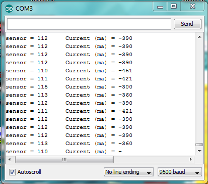
After uploading, run current through the sensor (e.g., power a small load). Open Serial Monitor (9600 baud) – you’ll see real-time current in amperes!
Note: Calibrate offsetVoltage with no load (should read ~2.5V). For AC current, take multiple samples and calculate RMS. Moreover, ensure proper wiring polarity and avoid exceeding rated current.
Wrapping up
In this post, we’ve covered all the fundamental aspects of the ACS712 Current Sensor Module. We trust that the information provided has been clear and insightful. Feel free to ask any questions you may have about this topic in the comment section below. We are here to help and provide additional clarification as needed.