Welcome, Developers & Engineers! We’re excited to have you here. This space is built for creators, problem-solvers, and tech enthusiasts like you. Whether you’re exploring projects, diving into code, or just visiting a site that speaks your language, you’re in the right place. In this blog, you will gain insightful knowledge of the Voltage Sensor Module. Moreover, understanding the basics of this simple yet essential module can greatly enhance your voltage monitoring and battery projects. So, let’s get started.
What is Voltage Sensor Module?
The Voltage Sensor Module is a basic resistive voltage divider module that allows safe measurement of higher DC voltages (up to 25V) using a microcontroller’s ADC pin (0-5V range). Consequently, it is widely used in Arduino projects to monitor battery levels, solar panels, power supplies, or any DC voltage source. This module uses two resistors (typically 30kΩ and 7.5kΩ) to divide the input voltage by 5. Therefore, it outputs a proportional lower voltage that is safe for direct connection to Arduino or ESP32 analog pins. Additionally, it is compact, low-cost, and requires no external power.
Working Principles of Voltage Sensor Module?
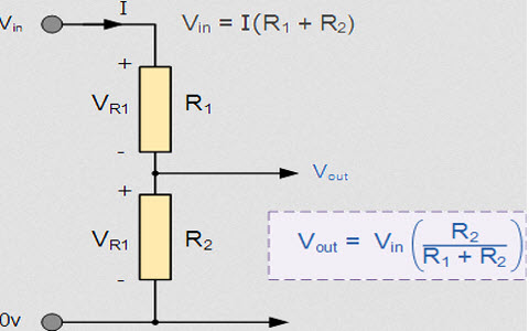
Voltage Division: First, the module consists of a simple voltage divider circuit with two resistors in series: R1 (30kΩ) connected to the input voltage and R2 (7.5kΩ) to ground. As a result, the output voltage at the junction is Vout = Vin × (R2 / (R1 + R2)).
Scaling: Moreover, with the common 30kΩ:7.5kΩ ratio, the division factor is exactly 5:1. Consequently, an input of 25V produces 5V output, and 12V input gives ~2.4V – perfect for 5V microcontrollers.
Measurement: In addition, the microcontroller’s ADC reads this scaled voltage and multiplies it back by 5 in code to get the original value.
Hardware Overview of Voltage Sensor Module?
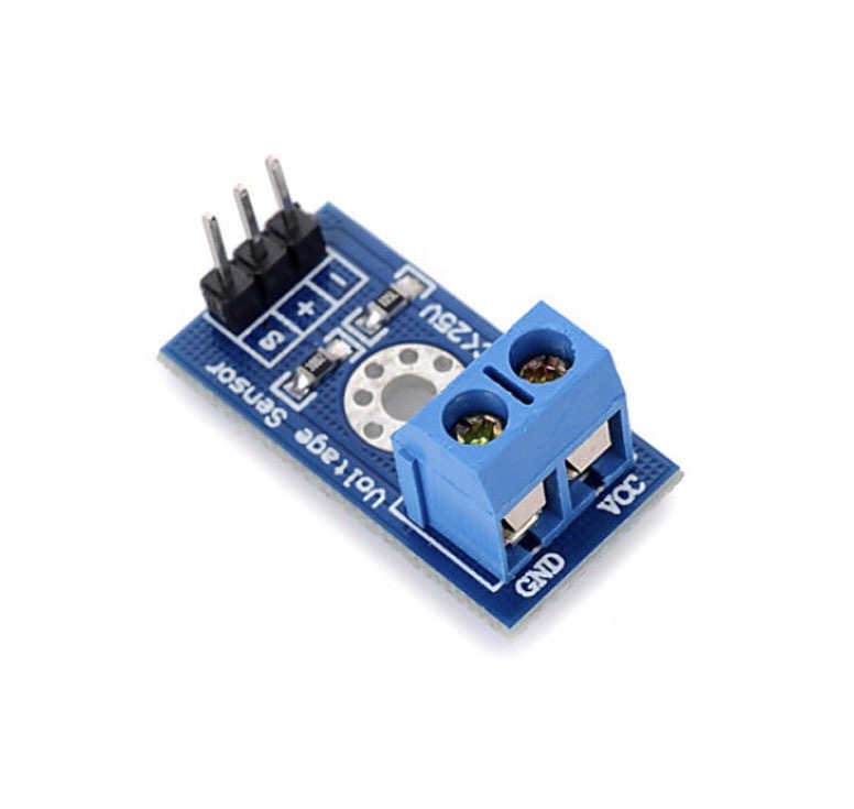
The module is a small PCB with three pins, two resistors, and screw terminals or header pins for input.
Input is applied across the + and – terminals (polarity matters for DC). As a result, it only measures DC voltage (positive).
Supporting Circuitry: Additionally, some versions include a trimming potentiometer for fine calibration, but most are fixed-ratio. Consequently, it’s completely passive and draws negligible current.
Technical Specifications of Voltage Sensor Module?
- Function: DC voltage measurement via resistive divider.
- Input Voltage Range: 0 to 25V DC.
- Output Voltage: 0 to 5V DC (proportional).
- Division Ratio: 5:1 (Vin = Vout × 5).
- Accuracy: ~1-2% (depends on resistor tolerance).
- Resistors: Typically 30kΩ and 7.5kΩ (ratio 5:1).
- Pinout: VCC (not used), GND, S (signal output), + and – input terminals.
- Operating Current: Very low (~0.8 mA at 25V).
- Size: Approximately 28mm x 14mm.
Voltage Sensor Module Pinout?
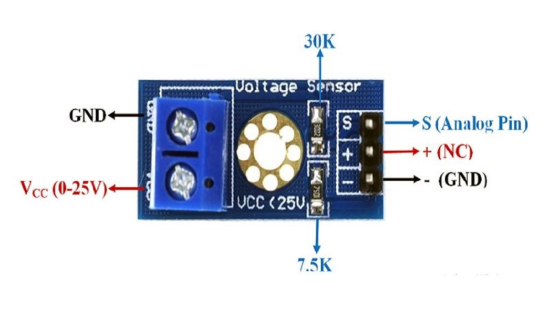
- –: Ground (connect to source negative)
- S (or OUT): Signal output to Arduino analog pin
- +: Positive input (0-25V)
- GND (or middle pin): Ground for output (connect to Arduino GND)
Basic Connections to Arduino:
- Input + : Connect to voltage source positive
- Input – : Connect to voltage source negative
- S : Connect to analog pin (e.g., A0)
- GND : Connect to Arduino GND
Real Life Uses and Applications of Voltage Sensor Module?
This simple module is perfect for monitoring DC power sources safely.
- Battery Level Monitoring: Tracks 12V car, LiPo, or lead-acid battery voltage.
- Solar Panel Monitoring: Measures output voltage in solar projects.
- Power Supply Testing: Checks stability of DC adapters.
- Robot Battery Management: Low-battery alerts.
- UPS Systems: Monitors backup battery status.
- Charging Circuits: Detects full charge voltage.
- IoT Devices: Reports voltage remotely via ESP32.
Using Voltage Sensor Module with Arduino
In this part, we will learn how you can use the Voltage Sensor Module with Arduino Uno, Nano, or Mega to measure DC voltage in just a few minutes – even if you’re a beginner.
What You Need:
- Any Arduino board (Uno recommended)
- Voltage Sensor Module
- Jumper wires
- DC voltage source (e.g., battery or power supply <25V)
Wiring Diagram:
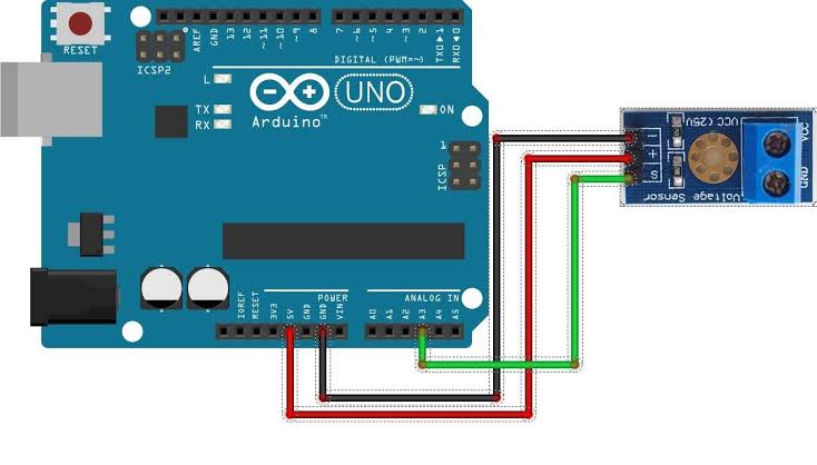
Connect the sensor in parallel with the voltage source.
Code:
No special library is required – just use analogRead(). Here’s a tested simple code – just copy-paste into your Arduino IDE.
#define VOLT_PIN A0    // Signal to analog pin A0

float ratio = 5.0;     // Division ratio (Vout * 5 = Vin)

void setup() {
  Serial.begin(9600);
  Serial.println("Voltage Sensor Ready!");
}

void loop() {
  int rawValue = analogRead(VOLT_PIN);
  float voltageOut = (rawValue / 1023.0) * 5.0;  // ADC to voltage
  float actualVoltage = voltageOut * ratio;

  Serial.print("Measured Voltage: ");
  Serial.print(actualVoltage, 2);
  Serial.println(" V");

  delay(1000);  // Read every second
}
Note: This is a basic example using standard Arduino functions – no external library needed.
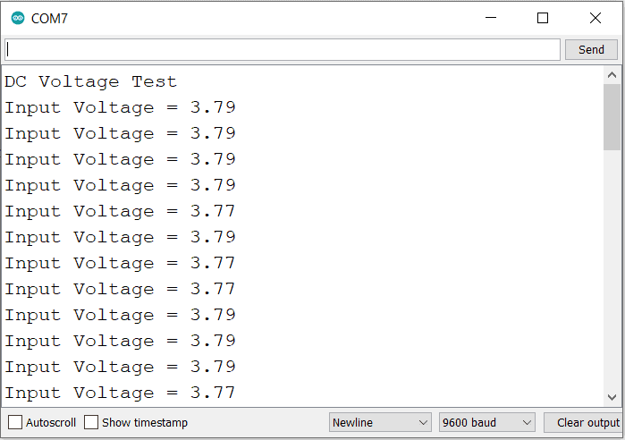
After uploading, open Serial Monitor (9600 baud). Apply a known voltage (e.g., 9V battery) – you’ll see the measured value close to actual!
Note: For better accuracy, calibrate with a multimeter and adjust the ratio. Use averaging for stable readings. Moreover, never exceed 25V input to avoid damage.
Wrapping up
In this post, we’ve covered all the fundamental aspects of the Voltage Sensor Module. We trust that the information provided has been clear and insightful. Feel free to ask any questions you may have about this topic in the comment section below. We are here to help and provide additional clarification as needed.