Welcome, Developers & Engineers! We’re excited to have you here. This space is built for creators, problem-solvers, and tech enthusiasts like you. Whether you’re exploring projects, diving into code, or just visiting a site that speaks your language, you’re in the right place. In this blog, you will gain insightful knowledge of the MAX31865 Temperature Sensor Module. Moreover, understanding the basics of the MAX31865 can greatly enhance your high-precision temperature measurement projects. So, let’s get started.
What is MAX31865 Temperature Sensor Module?
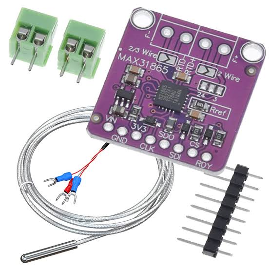
The MAX31865 is a precision resistance-to-digital converter module specifically designed for Platinum Resistance Temperature Detectors (RTDs) like PT100 and PT1000. Consequently, it is widely used in industrial and hobbyist projects requiring accurate temperature sensing over a wide range. Manufactured by Maxim Integrated (now Analog Devices), this module converts the small resistance changes of an RTD into a digital value via SPI protocol. Therefore, it is easy to interface with microcontrollers like Arduino, ESP32, or Raspberry Pi. Additionally, breakout boards include reference resistors, filtering, and fault detection for reliable operation.
Working Principles of MAX31865 Temperature Sensor Module?
RTD Measurement: First, Platinum RTDs (PT100/PT1000) change resistance linearly with temperature (≈0.385 Ω/°C for PT100). As a result, the MAX31865 excites the RTD with a precise current and measures the voltage drop.
Ratio-metric Conversion: Moreover, it uses a high-precision reference resistor to perform ratiometric measurement, canceling out errors from excitation current variations. Consequently, the 15-bit ADC provides excellent resolution (~0.03125°C).
Fault Detection: In addition, the module detects open/short circuits, over/under voltage, and RTD faults automatically.
Digital Interface: Furthermore, SPI communication allows configuration of 2/3/4-wire modes, 50/60 Hz filtering, and one-shot or continuous conversion.
Hardware Overview of MAX31865 Temperature Sensor Module?
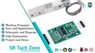
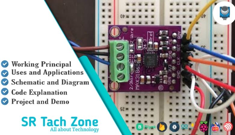
The MAX31865 module is a small breakout board with the MAX31865 IC, screw terminals for RTD connection, and SPI pins.
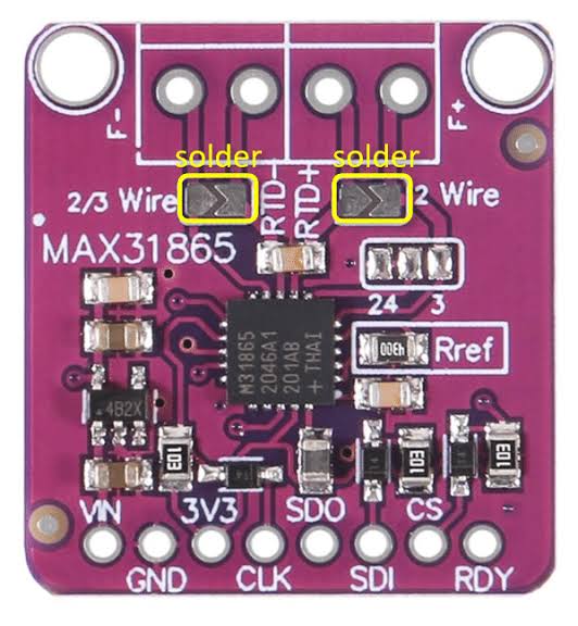
Supports 2-wire, 3-wire, or 4-wire RTD configurations (4-wire is most accurate). As a result, it compensates for lead wire resistance.
Supporting Circuitry: Additionally, includes a precision reference resistor (400Ω for PT100, 4000Ω for PT1000) and filtering capacitors.
Consequently, wiring is straightforward with proper RTD connection.
Technical Specifications of MAX31865 Temperature Sensor Module?
- Function: RTD-to-digital converter for PT100/PT1000.
- Supported RTDs: PT100 (100Ω @ 0°C), PT1000 (1000Ω @ 0°C).
- Temperature Range: -200°C to +850°C (limited by RTD).
- Resolution: 0.03125°C (15-bit).
- Accuracy: ±0.5°C (with proper calibration and 4-wire).
- Communication: SPI (up to 5 MHz).
- Operating Voltage: 3.3V to 5V (module), chip 3.0V-3.6V.
- Current Consumption: ~2 mA.
- Fault Detection: Open/short RTD, over/under voltage.
- Pinout: VCC, GND, SCL, SDA (MISO), MOSI, CS, optional 3.3V out, RDY.
MAX31865 Temperature Sensor Module Pinout?
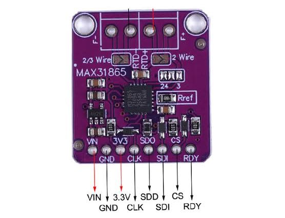
- VCC: Power supply (3.3V-5V)
- GND: Ground
- SCL (SCK): SPI clock
- SDA (SDI): SPI data in (MOSI)
- SDO (MISO): SPI data out
- CS: Chip select
- RDY (optional): Conversion ready interrupt
- RTD Terminals: 2/3/4-wire connections
Basic Connections to Arduino:
- VCC: Connect to 3.3V or 5V
- GND: Connect to Arduino GND
- SCL: Connect to pin 13 (SCK on Uno)
- SDA: Connect to pin 11 (MOSI)
- SDO: Connect to pin 12 (MISO)
- CS: Connect to any digital pin (e.g., 10)
Real Life Uses and Applications of MAX31865 Temperature Sensor Module?
The MAX31865 provides industrial-grade accuracy ideal for precise temperature control.
- Industrial Process Control: Monitors reactors, ovens, or HVAC systems.
- 3D Printer Hotends: Accurate bed/nozzle temperature for better prints.
- Scientific Experiments: Lab-grade temperature logging.
- Food Processing: Precise cooking or fermentation monitoring.
- Environmental Monitoring: Soil or water temperature in agriculture.
- Medical Equipment: Accurate body or incubator temperature sensing.
- Home Brewing: Controls mash or fermentation temperatures.
Using MAX31865 Temperature Sensor Module with Arduino
In this part, we will learn how you can use MAX31865 with Arduino Uno, Nano, or Mega to read accurate RTD temperature in just a few minutes – even if you’re a beginner.
What You Need:
- Any Arduino board (Uno recommended)
- MAX31865 Module
- PT100 or PT1000 RTD probe
- Jumper wires
Wiring Diagram:
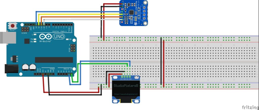
Use 3-wire or 4-wire connection for best accuracy.
Code:
Install “Adafruit MAX31865” library via Arduino IDE Library Manager before uploading. Here’s a tested simple code – just copy-paste into your Arduino IDE.
#include <Adafruit_MAX31865.h>

// Use hardware SPI: CS, DI (MISO), DO (MOSI), CLK
Adafruit_MAX31865 thermo = Adafruit_MAX31865(10);  // CS pin 10

#define RREF      430.0   // Reference resistor (430Ω for PT100)
#define RNOMINAL  100.0   // RTD nominal resistance at 0°C

void setup() {
  Serial.begin(115200);
  Serial.println("MAX31865 RTD Sensor Ready!");

  thermo.begin(MAX31865_3WIRE);  // 2WIRE, 3WIRE, or 4WIRE
}

void loop() {
  float temp = thermo.temperature(RNOMINAL, RREF);

  uint8_t fault = thermo.readFault();
  if (fault) {
    Serial.print("Fault 0x"); Serial.println(fault, HEX);
    thermo.clearFault();
  } else {
    Serial.print("Temperature: ");
    Serial.print(temp);
    Serial.println(" °C");
  }

  delay(1000);
}
Credit: This example code is adapted from the official examples in the Adafruit MAX31865 library by Adafruit Industries. Library available here: https://github.com/adafruit/Adafruit_MAX31865
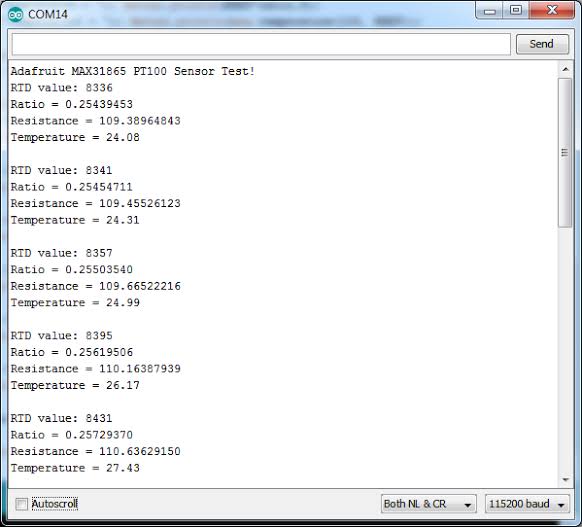
After uploading, open Serial Monitor (115200 baud). You’ll see accurate temperature readings updating every second. Any faults will be reported!
Note: Match RREF to your board’s reference resistor (usually 400Ω or 430Ω). Use 4-wire for highest accuracy. Moreover, calibrate with known temperatures (e.g., ice water 0°C, boiling 100°C) for best results.
Wrapping up
In this post, we’ve covered all the fundamental aspects of the MAX31865 Temperature Sensor Module. We trust that the information provided has been clear and insightful. Feel free to ask any questions you may have about this topic in the comment section below. We are here to help and provide additional clarification as needed.