Welcome, Developers & Engineers! We’re excited to have you here. This space is built for creators, problem-solvers, and tech enthusiasts like you. Whether you’re exploring projects, diving into code, or just visiting a site that speaks your language. In this blog, you will gain insightful knowledge of the MPU6050 Sensor Module. Basics of the MPU6050 can greatly enhance your motion-sensing projects and applications. So, let’s start.
What is MPU6050 Sensor Module?
The MPU6050 is a popular 6-axis inertial measurement unit (IMU) that combines a 3-axis accelerometer and a 3-axis gyroscope in a single compact chip. It’s widely used in electronics projects to detect motion, orientation, and rotation. Manufactured by InvenSense (now part of TDK), this module communicates via I2C protocol, making it super easy to connect with microcontrollers like Arduino, ESP32, or Raspberry Pi. It also includes a built-in temperature sensor and a Digital Motion Processor (DMP) for advanced calculations like sensor fusion.
Working Principles of MPU6050 Sensor Module?
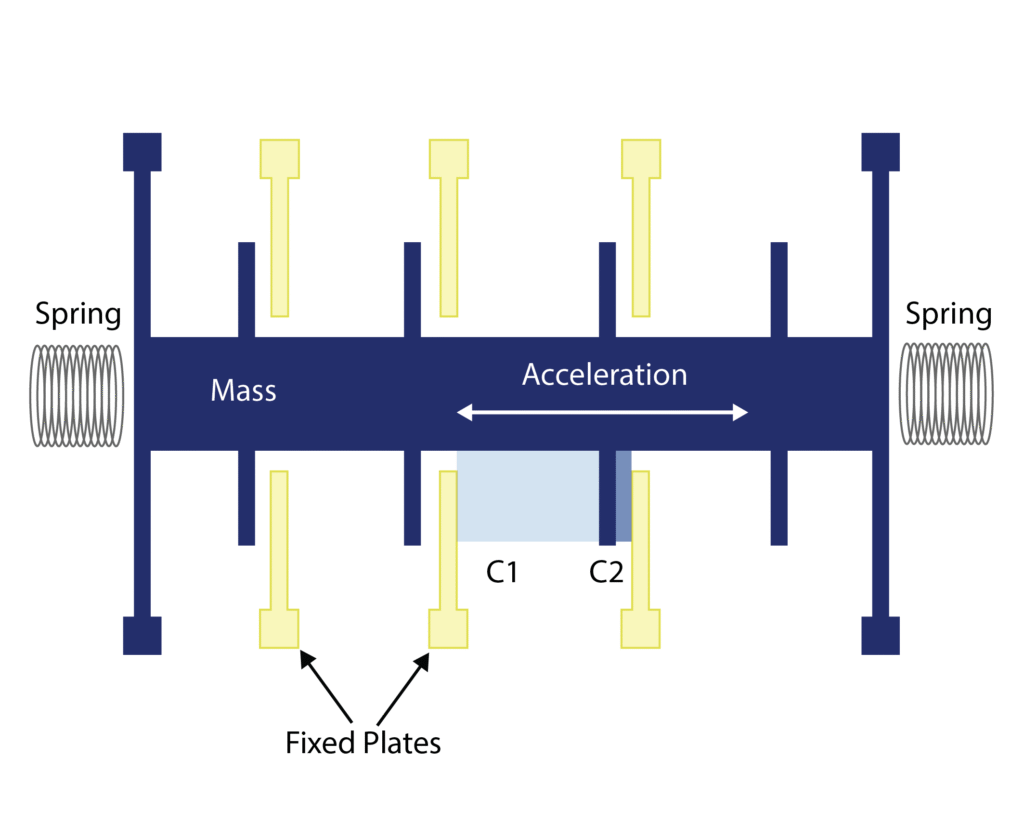
Accelerometer Measurement: The accelerometer in the MPU6050 uses MEMS (Micro-Electro-Mechanical Systems) technology. It measures linear acceleration along the X, Y, and Z axes by detecting the deflection of a tiny proof mass suspended on springs. When the sensor accelerates, the mass moves, changing capacitance between fixed and movable plates. This change is converted to digital values representing acceleration in g (gravity units), with programmable ranges like ±2g, ±4g, ±8g, or ±16g.
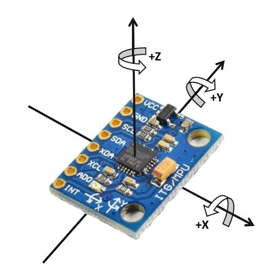
Gyroscope Measurement: The gyroscope measures angular velocity (rotation rate) around the three axes using the Coriolis effect on vibrating MEMS structures. When the sensor rotates, the vibrating mass experiences a force perpendicular to the vibration and rotation, which is detected and converted to degrees per second (°/s). Ranges include ±250, ±500, ±1000, or ±2000 °/s.
Digital Communication: The MPU6050 uses I2C (Inter-Integrated Circuit) protocol for communication. It has a default address of 0x68 (or 0x69 if AD0 pin is high). Data is read from registers containing raw 16-bit values for acceleration, gyro, and temperature. The on-chip DMP can fuse data for more accurate orientation without burdening the microcontroller.
Hardware Overview of MPU6050 Sensor Module?
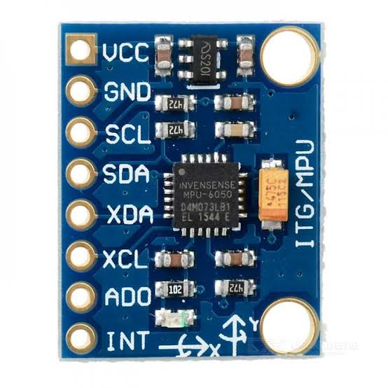
The MPU6050 module is a small breakout board (usually called GY-521) that includes the MPU6050 chip, a 3.3V regulator, pull-up resistors for I2C lines, and decoupling capacitors.
The core is the 24-pin QFN package MPU6050 IC with integrated sensors and processor. Modules often have 8 pins for easy connection.
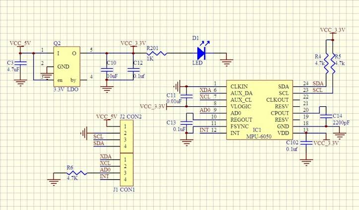
Supporting Circuitry: Most modules include a low-dropout regulator to accept 3-5V input while the chip runs at 3.3V. Pull-up resistors (typically 4.7kΩ) on SDA and SCL lines ensure stable I2C communication. No external components are usually needed beyond power and I2C connections, though short wires are recommended for reliable readings.
Technical Specifications of MPU6050 Sensor Module?
- Function: 6-axis motion tracking (3-axis accel + 3-axis gyro) with temperature sensor.
- Output: Digital I2C interface, 16-bit ADC resolution.
- Sensor Type (Accelerometer): MEMS capacitive, ranges ±2g to ±16g (programmable).
- Sensor Type (Gyroscope): MEMS vibrating structure, ranges ±250°/s to ±2000°/s (programmable).
- Pinout: 8 pins (VCC, GND, SCL, SDA, XDA, XCL, AD0, INT).
- Communication: I2C (up to 400kHz), address 0x68/0x69.
- Measurement Specifications for Accelerometer: Sensitivity up to 16384 LSB/g (±2g), low noise.
- Measurement Specifications for Gyroscope: Sensitivity up to 131 LSB/°/s (±250°/s), low drift.
- Temperature Sensor: Range -40°C to +85°C with ±1°C accuracy.
- Operating Voltage: 3V to 5V (module), chip 2.3V-3.6V.
- Current Consumption: ~3.9mA in full operation, low-power modes available.
- Data Format: 16-bit two’s complement for accel/gyro, raw temperature value.
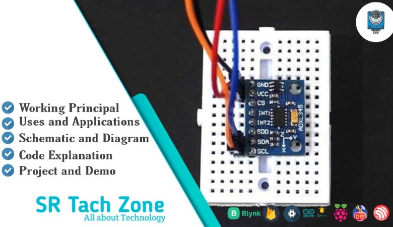
MPU6050 Sensor Module Pinout?
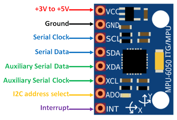
- VCC: Power supply (3-5V)
- GND: Ground
- SCL: I2C clock line (connect to Arduino A5 or SCL pin)
- SDA: I2C data line (connect to Arduino A4 or SDA pin)
- AD0: Address select (low for 0x68, high for 0x69)
- INT: Interrupt output (optional)
- XCL/XDA: Auxiliary I2C for external sensors (optional)
Basic Connections to Arduino:
- VCC: Connect to 5V on Arduino
- GND: Connect to Arduino GND
- SCL: Connect to A5 (Uno) or SCL pin
- SDA: Connect to A4 (Uno) or SDA pin
Real Life Uses and Applications of MPU6050 Sensor Module?
The MPU6050 is a low-cost, reliable 6-DOF IMU perfect for hobbyist, educational, and prototype projects involving motion detection.
- Self-Balancing Robots: Uses fused accel and gyro data to keep two-wheeled robots upright with PID control.
- Drone Flight Controllers: Stabilizes quadcopters by measuring tilt and rotation for precise hovering.
- Gesture-Controlled Devices: Detects hand movements for controlling robots, games, or smart home appliances.
- Fitness Trackers: Counts steps, monitors orientation for activity recognition in wearable DIY projects.
- Virtual Reality Headsets: Tracks head movement for immersive experiences in low-cost VR setups.
- Vibration Monitoring: Detects machine vibrations or earthquakes in industrial or home alert systems.
- Camera Stabilizers: Builds handheld gimbals that counteract shakes for smooth video.
Using MPU6050 Sensor Module with Arduino
In this part, we will learn how you can use MPU6050 with Arduino Uno, Nano, or Mega to read acceleration, angular velocity, and temperature in just a few minutes – even if you’re a beginner.
What You Need:
- Any Arduino board (Uno recommended)
- MPU6050 module (GY-521)
- Jumper wires
- Breadboard (optional)
Wiring Diagram:
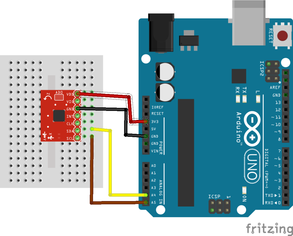
Connect directly via I2C – no extra resistors needed as they’re on the module.
Code:
Install “Adafruit MPU6050” and “Adafruit Unified Sensor” libraries via Arduino IDE Library Manager before uploading. Here’s a tested simple code – just copy-paste into your Arduino IDE.
#include <Adafruit_MPU6050.h>
#include <Adafruit_Sensor.h>
#include <Wire.h>

Adafruit_MPU6050 mpu;

void setup() {
  Serial.begin(115200);
  while (!Serial) {
    delay(10); // Wait for serial port
  }

  if (!mpu.begin()) {
    Serial.println("Failed to find MPU6050 chip!");
    while (1) {
      delay(10);
    }
  }
  Serial.println("MPU6050 Found!");

  mpu.setAccelerometerRange(MPU6050_RANGE_8_G);
  mpu.setGyroRange(MPU6050_RANGE_500_DEG);
  mpu.setFilterBandwidth(MPU6050_BAND_21_HZ);

  Serial.println("MPU6050 is ready!");
}

void loop() {
  sensors_event_t a, g, temp;
  mpu.getEvent(&a, &g, &temp);

  Serial.print("Acceleration X: ");
  Serial.print(a.acceleration.x);
  Serial.print(" m/s^2 | Y: ");
  Serial.print(a.acceleration.y);
  Serial.print(" | Z: ");
  Serial.println(a.acceleration.z);

  Serial.print("Rotation X: ");
  Serial.print(g.gyro.x);
  Serial.print(" rad/s | Y: ");
  Serial.print(g.gyro.y);
  Serial.print(" | Z: ");
  Serial.println(g.gyro.z);

  Serial.print("Temperature: ");
  Serial.print(temp.temperature);
  Serial.println(" °C");

  Serial.println("");
  delay(2000); // Update every 2 seconds
}
Credit: This example code is adapted from the official “basic_readings” sketch in the Adafruit MPU6050 library by Adafruit Industries. Library available here: https://github.com/adafruit/Adafruit_MPU6050
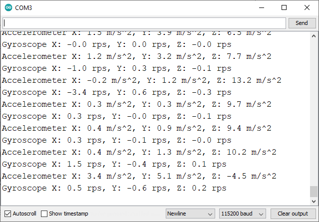
After uploading the code to your Arduino, open the Serial Monitor (Ctrl+Shift+M), set baud rate to 115200, and you’ll see live readings like acceleration in m/s², rotation in rad/s, and temperature in °C updating every 2 seconds. Tilt or rotate the sensor to see values change!
Note: If you get “Failed to find MPU6050 chip!”, double-check wiring, use short wires (<20cm), and ensure I2C pins are correct. For more advanced features like angle calculation, try complementary filters or Kalman filters in code.
Wrapping up
In this post, we’ve covered all the fundamental aspects of the MPU6050 Sensor Module. We trust that the information provided has been clear and insightful. Feel free to ask any questions you may have about this topic in the comment section below. We are here to help and provide additional clarification as needed.